High-definition dual video decoder and decoding method, and digital broadcasting receiver using the same

a dual-channel video and decoding technology, applied in the field of high-definition dual-channel video decoding and decoding methods, and digital broadcasting receivers using the same, can solve the problems of increased cost, high cost, and difficulty in stably performing the decoding for the two channels without image loss, and achieve high cost and unstable operation.

Inactive Publication Date: 2005-06-02
LG ELECTRONICS INC
View PDF1 Cites 41 Cited by
  • Summary
  • Abstract
  • Description
  • Claims
  • Application Information

AI Technical Summary

Benefits of technology

[0024] An object of the present invention is to provide a HD dual video decoder and a decoding method in which a drawback of a high cost and an unstable operation caused by a mutual interference of a dual video can be solved.
[0025] Another object of the present invention is to provide a HD dual video decoder

Problems solved by technology

Even though encoding is performed using the MPEG, which is a technology of digital video compression generally having a good compression efficiency, a large size of an operational circuit and a complicated controlling circuit are required to embody a video decoder for restoring the HD video with much data in real time.
Accordingly, a cost and a performance of the video decoder depend on whether or not how much precisely and effectively the two portions are designed.
Accordingly, a cost is increased.
However, the conventional art has a difficulty in stably performing the decoding for the two channels without the image l

Method used


Image

  • High-definition dual video decoder and decoding method, and digital broadcasting receiver using the same
  • High-definition dual video decoder and decoding method, and digital broadcasting receiver using the same
  • High-definition dual video decoder and decoding method, and digital broadcasting receiver using the same

Examples


Embodiment Construction

[0064] Reference will now be made in detail to the preferred embodiments of the present invention, examples of which are illustrated in the accompanying drawings. Wherever possible, the same reference numbers will be used throughout the drawings to refer to the same or like parts.

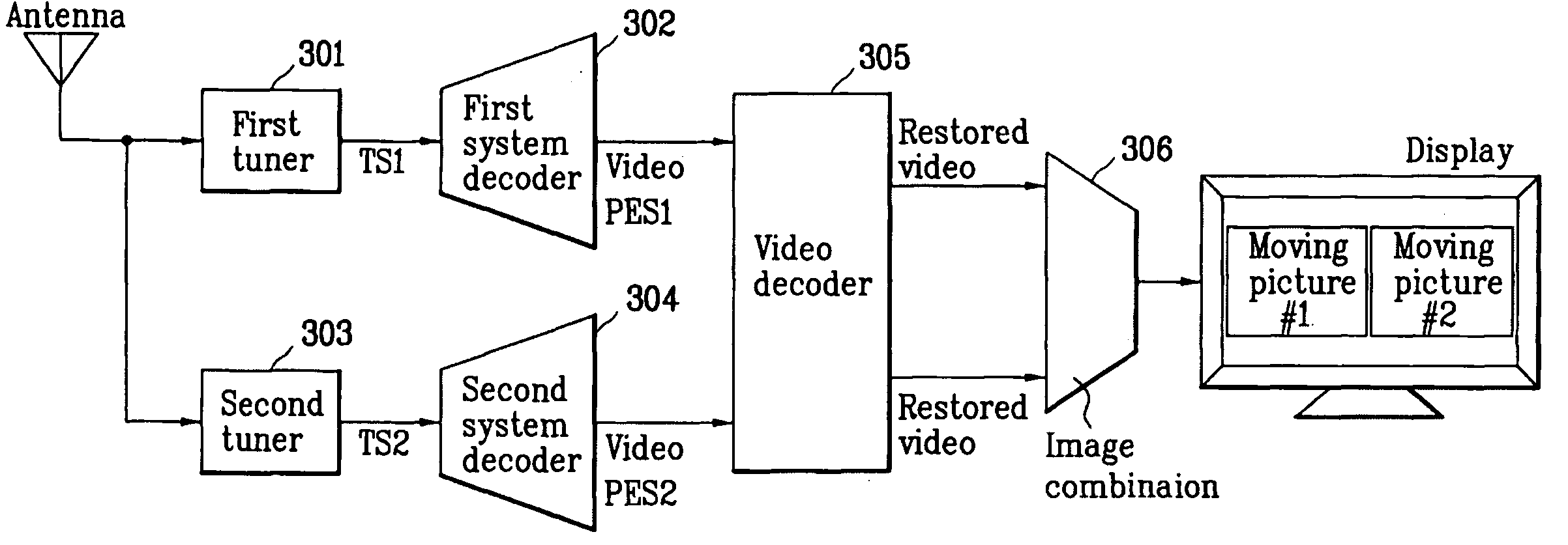
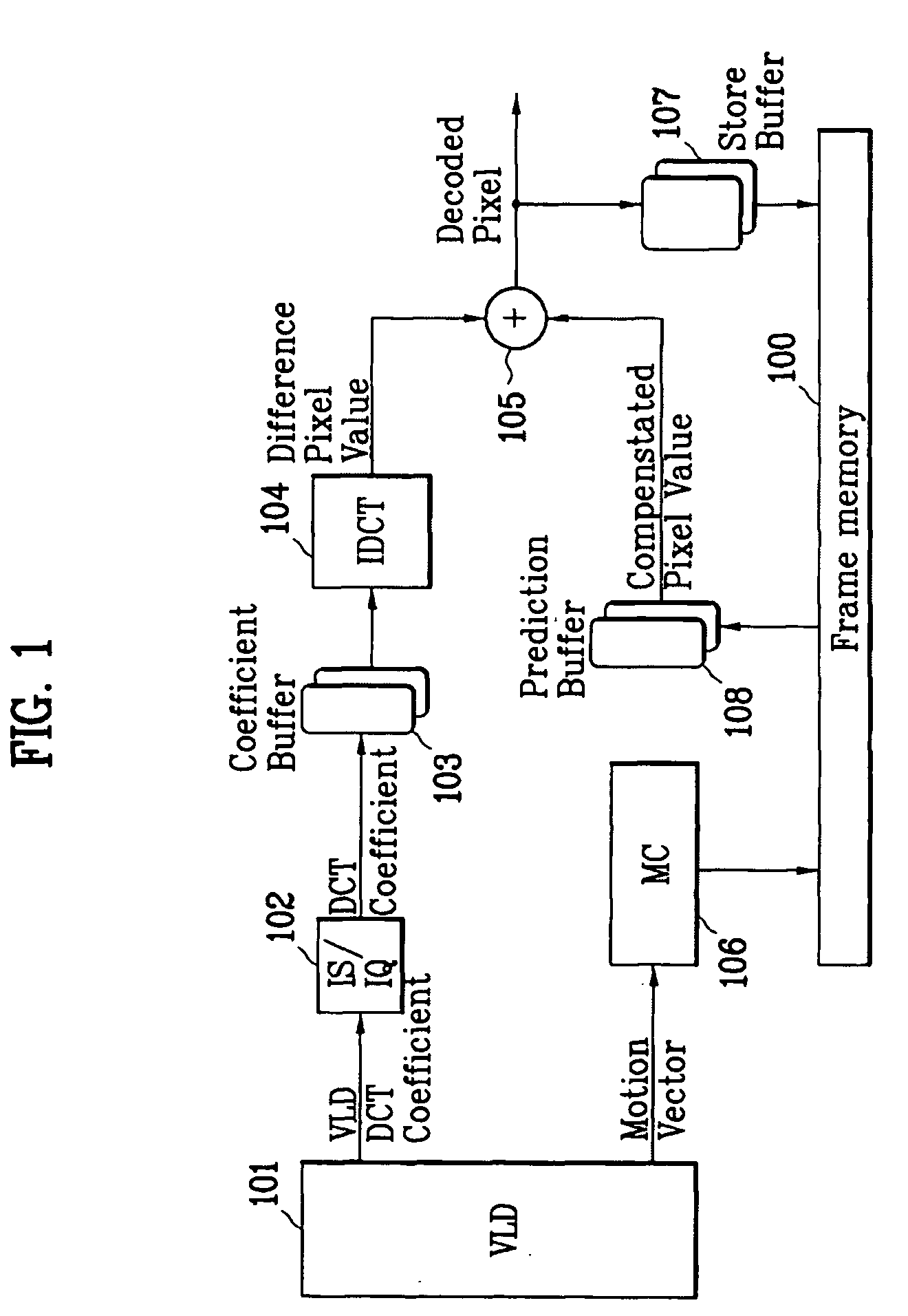
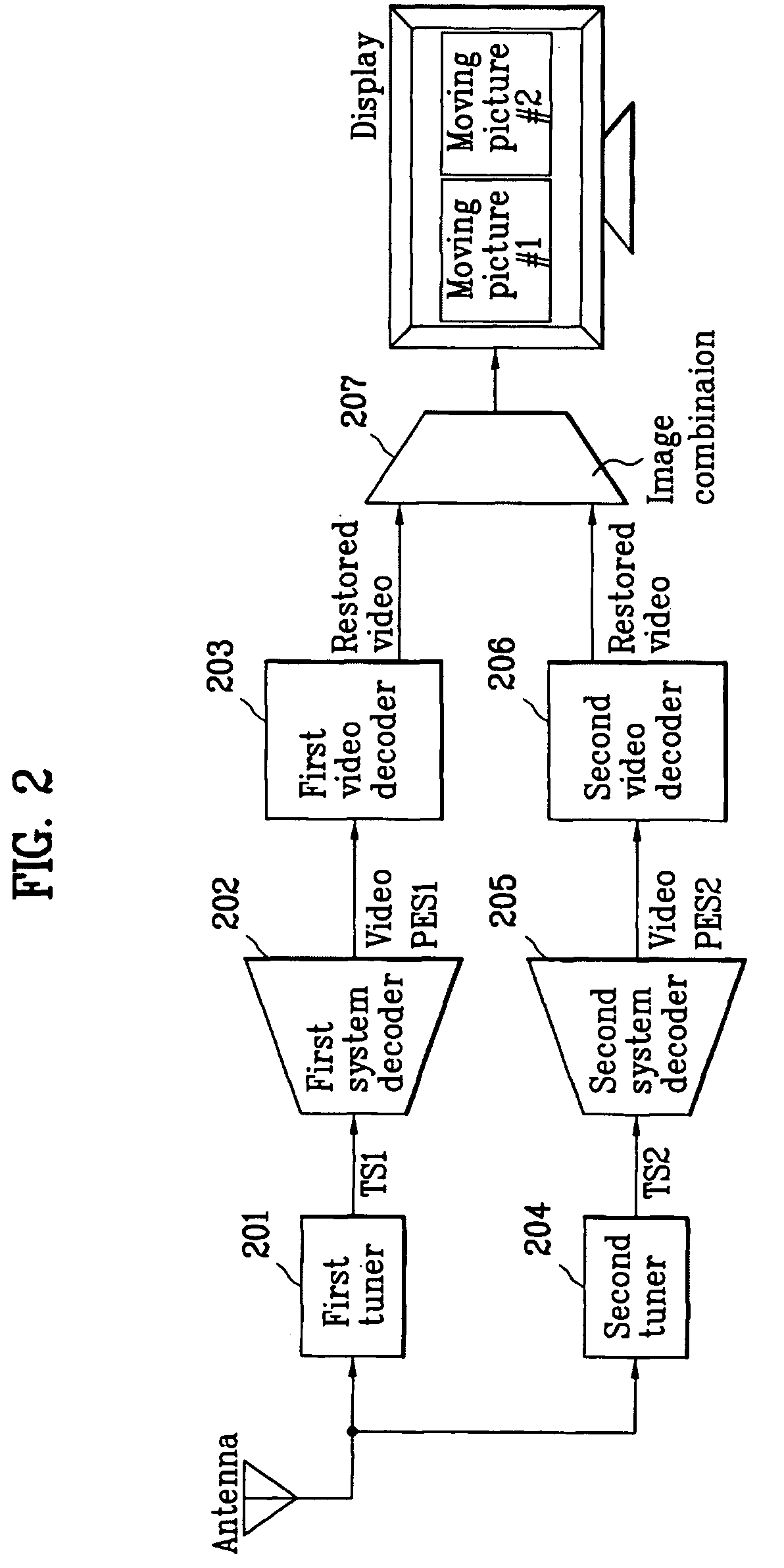
[0065]FIG. 3 is a whole schematic view illustrating a digital broadcasting receiver having a two-channel video decoder according to the present invention, and FIG. 4 is a detailed block diagram illustrating a two-channel video decoder of FIG. 3.

[0066] Referring to FIG. 3, the digital broadcasting receiver includes two tuners 301 and 303, system decoders 302 and 304, and one video decoder 305 to concurrently decode two High-Definition (HD) video signals.

[0067] The video decoder 305 additionally includes a screen combining unit 306 at its output terminal to combine and display concurrently the decoded two HD video signals.

[0068] The video decoder 305 shares main blocks as shown in FIG. 4, and allows the d...


PUM


Abstract

A dual video decoder of a digital broadcasting receiver is provided. The decoder includes: a first PES decoder for decoding a first video PES outputted from a first system decoder, into a first video ES; a second PES decoder for decoding a second video PES outputted from a second system decoder, into a second video ES; a VBV (Video Buffer Verifier) buffer memory divided into a first video ES region and a second video ES region; a decoding controller for outputting a control signal to determine a to-be-decoded video ES among the first and second video ESs, and independently decode the first and second video ESs in a single decoding unit; and the single decoding unit for reading the to-be-decoded video ES from the corresponding region of the VBV buffer memory.

Description

[0001] This application claims the benefit of the Korean Application No. 10-2003-0085959 filed on Nov. 29, 2003, which is hereby incorporated by reference. BACKGROUND OF THE INVENTION [0002] 1. Field of the Invention [0003] The present invention relates to a digital broadcasting receiver for restoring a digital video compressed according to a standard of a Moving Picture Experts Group (MPEP), and more particularly, to a dual video decoder and a decoding method in which two High-Definition (HD) videos transmitted through different paths or channels are concurrently restored and displayed on a screen by using one video decoder. [0004] 2. Discussion of the Related Art [0005] Moving Picture Experts Group (MPEP) standard, which is widely used as a moving picture compression way in a variety of field, is classified into a profile and a level depending on its application purpose. Accordingly, in order to embody a high quality of video, the moving picture should be encoded in a video size a...

Claims


Application Information

Patent Timeline
IPC IPC(8): H04N5/44H04N7/24H04N5/45H04N7/12H04N7/26
CPCH04N5/4401H04N5/45H04N19/16H04N19/44H04N19/39H04N21/4343H04N21/4263H04N21/4307H04N21/4316H04N21/44004H04N19/42H04N21/426H04N21/43072
Inventor IM, JIN SEOK
Owner LG ELECTRONICS INC
Why Eureka
Try Eureka