Roller chain transmission device

Active Publication Date: 2005-06-02
TSUBAKIMOTO CHAIN CO
View PDF3 Cites 16 Cited by
  • Summary
  • Abstract
  • Description
  • Claims
  • Application Information

AI Technical Summary

Benefits of technology

[0016] The radius r1 of the arc of the tooth bottom portion of the first teeth, in the expression 0.505 Dr<r1<0.505 Dr+0.069 3{square root} Dr, is based on ISO “B” standard BS 228 as defined by the expression 3 in the above mentioned relational expression. When the radius r2 of an arc of the tooth bottom portion of the second teeth is smaller than r1, a the engagement noise reduction effect is increased. However, if r2 is equal to or less than 0.50 Dr, it becomes smaller than the outer diameter of the roller, which causes undesirable jumping of the sprocket teeth.
[0017] When the chain pins have different diameters and are randomly arranged in the longitudinal direction of the chain, the engagement noise reduction is further enhanced. Furthermore, when both the first and second pins are present in a quantity of 20% or more with respect to the total number of pins in the roller chain, and the diameters d1 of the fir

Problems solved by technology

However, it has not been shown that the above-mentioned conventional low noise roller chain transmissions reduce engagement noise to any significant degree.
Furthermore, it has been shown that a particularly large engagement noi

Method used


Image

  • Roller chain transmission device
  • Roller chain transmission device
  • Roller chain transmission device

Examples


Example

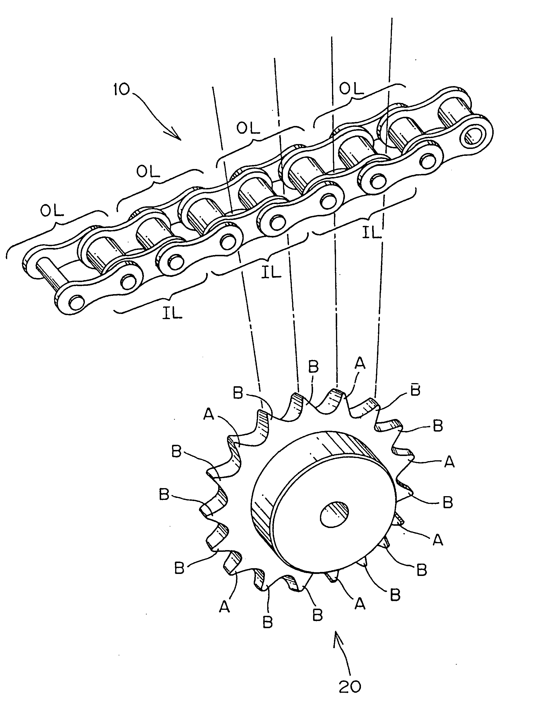
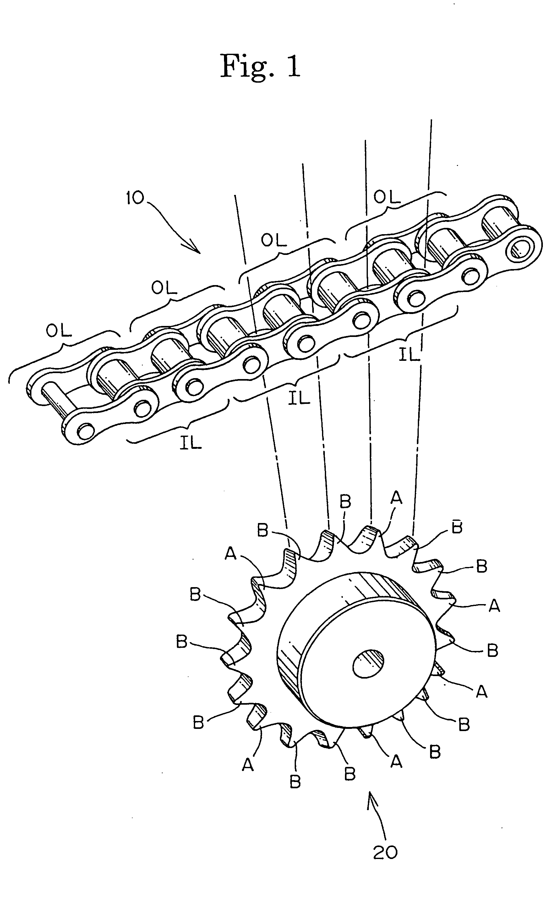
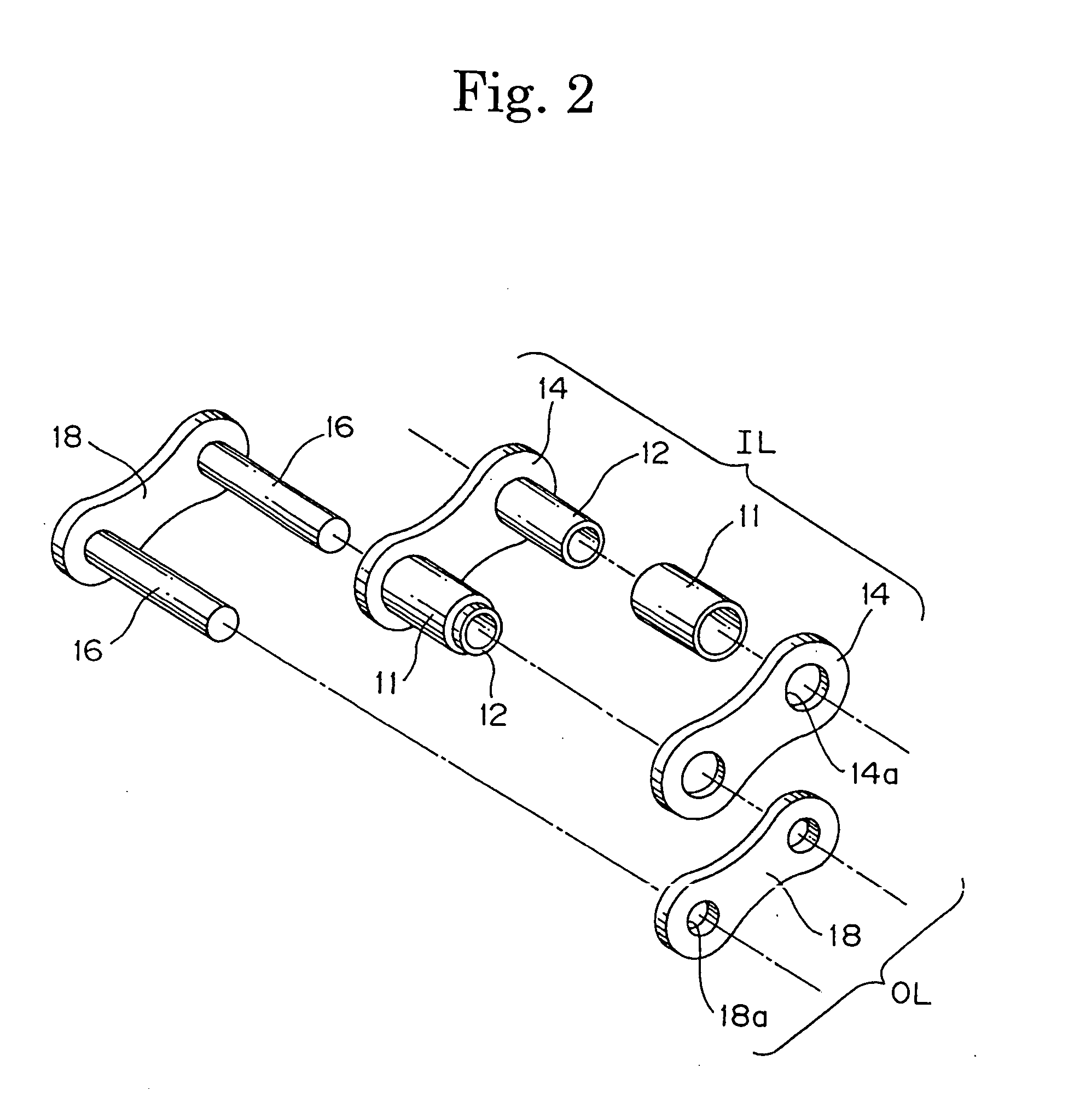
[0025] The roller chain transmission device according to the invention comprises a roller chain, the details of which are shown in FIG. 2. The chain includes an inner link IL, comprising a pair of inner plates 14 with bushing holes 14a, into which the ends of two cylindrical bushings 12 are respectively press-fit. A roller 11 fits rotatably on each bushing 12. Pins 16 are press fit in pin holes 18a of a pair of outer link plates 18, which are disposed adjacent the outsides of the inner link plates. As seen in FIG. 2, one of the pins 16 extends through one of the bushings of the inner link IL, fitting loosely therein so that the outer link OL is in articulating relationship with the inner link IL. Similar inner and outer links are articulably connected to one another in alternating relationship to form a flexible roller chain 10, as shown in FIG. 1. The flexible roller chain can engage a driving sprocket 20, and at least one driven sprocket (not shown) to form a chain transmission in...


PUM


Abstract

A roller chain transmission comprises a sprocket having at least first teeth and second teeth having different tooth forms, the first teeth and second teeth being randomly arranged, and the number of the second teeth not exceeding four times of the number of the first teeth. The roller chain may also have pins of slightly differing diameters, randomly arranged along the length of the chain.

Description

FIELD OF THE INVENTION [0001] This invention relates to roller chain transmissions of the kind used for power transmission in automobiles, conveyors, and other industrial machinery. The invention relates particularly to a roller chain transmission use in the timing drive (i.e, the camshaft drive) of an automobile engine. BACKGROUND OF THE INVENTION [0002] In recent years, metal roller chains have come into increasing used in power transmissions, in automobile engines and in other machines, as a result of high loads, high speeds, and the demand for maintenance-free operation. Roller chain transmissions have displaced toothed belt transmissions to a large extent. [0003] A typical roller chain transmission device comprises a roller chain including inner and outer links. Each inner link comprises a pair of inner link plates, two bushings, ends of which are press-fit into bushing holes formed in the inner link plates, and a roller rotatable on the outside of each bushing. Each of the out...

Claims


Application Information

Patent Timeline
IPC IPC(8): F16G13/02F16G13/06F16H7/06F16H55/08F16H55/30
CPCF16G13/06F16H55/30F16H55/08F16H7/06
Inventor OKABE, ISAMU
Owner TSUBAKIMOTO CHAIN CO
Why Eureka
Try Eureka