Aneurysm buttress arrangement

a technology for aneurysms and scaffolds, applied in the field of aneurysm buttress arrangement, can solve the problems of more thoroughly developed embolus, risk of coil migration out of the entrance zone of the aneurysm and into the feeding vessel, and hemorrhagic stroke, and achieve the effect of facilitating the sliding of the scaffold

Inactive Publication Date: 2005-06-02
NIAGARA GORGE MEDICAL DEVICES
View PDF6 Cites 93 Cited by
  • Summary
  • Abstract
  • Description
  • Claims
  • Application Information

AI Technical Summary

Benefits of technology

[0019] The buttress scaffold arrangement is introduced adjacent the aneurysm through a microcatheter pushed into the subject parent vessel, having its distalmost end placed adjacent the neck of the aneurysm. The distal tracking tip on the distal end of the scaffold may assist in directing that scaffold further downstream in the parent vessel distal of the microcatheter which delivered it. As the buttress scaffold is preferably delivered adjacent the neck of the aneurysm, it is permitted to expand to the diameter of the parent vessel.
[0021] A further embodiment of the buttress scaffold of the present invention is comprised of a plurality of layers of helically wound wires defining that mesh. The distal end of that scaffold being sloped into and attached to the extended distal tracking tip to help facilitate steering of that scaffolding within the parent vessel.
[0022] A further embodiment of the present invention contemplates the pushwire at the proximal end of the buttress scaffold to be hollow, with a thin control wire extending therethrough. The control wire is elongated and extends out the proximalmost end of the scaffold pushwire. The control wire has a distalmost end fixed to the distalmost end of the scaffold. The control wire may be moved longitudinally relative to the delivery wire / pushwire of the scaffold. Movement of the control wire relative to the delivery wire / pushwire permits dimensional control of the scaffold and facilitates advance of the distal tracking tip of the scaffold within the parent vessel. The internal control wire within the delivery wire / pushwire of the scaffold may be rotated about its longitudinal axis so as to effect rotation of the scaffold or a winding thereof relative to the pushwire so as to effect radial and / or longitudinal dimensional changes of that scaffold depending upon the “handedness” of the helical coil or braid making up that scaffold.
[0023] A further embodiment of that scaffold, comprises at least a portion of the cylindrical section thereof which may be wrapped within a thin polymeric film to facilitate movement of that scaffold, within the parent vessel or to enhance the buttressing effect of that scaffold adjacent the neck opening of the aneurysm. The cells defining the mesh and any polymeric film would be pierceable by the adjacent microcatheter delivery wire advancing into the aneurysm itself. The film may also be foraminous, to permit a microcatheter or medicaments to be delivered therethrough. The film also facilitates delivery of a microcatheter around the outside thereof and into the aneurysm.
[0027] The invention may also comprise a method of buttressing an intracranial aneurysm in a vessel wall, comprising the steps of: transluminally positioning a scaffold out of a delivery catheter, the scaffold having a proximal end and a distal end arranged onto a near distal of a delivery wire across the opening of an aneurysm; expanding the scaffold from a contracted diameter to engage the vessel wall by a spacing open of helically wound wire coils comprising the scaffold; introducing an embolitic agent into the aneurysm through a cell between adjacent wires comprising the coils; permitting blood to flow through the cells of the scaffold subsequent to the introduction of the embolitic agent into the aneurysm; and withdrawing the scaffold from its position adjacent the aneurysm. The method may also comprise one or more of the following steps of: placing a thin film about the scaffold prior to positioning of the scaffold adjacent the aneurysm; inserting a balloon within the scaffold prior to positioning of the scaffold adjacent the aneurysm; arranging the delivery wire to have a central lumen therethrough; placing a control wire through the lumen in the delivery wire; extending the control wire through the scaffold distally; and attaching the control wire to a distalmost end of the scaffold; extending the control wire distally of the scaffold so as to function as a distal tracking wire; moving the control wire so as to vary the size and shape of the scaffold; tapering the distal and proximal ends of the scaffold to facilitate sliding of the scaffold out of and back into the delivery catheter.

Problems solved by technology

Aneurysms are often a site of internal bleeding and, catastrophically, result in hemorrhagic strokes.
However, after, or perhaps during, delivery of such a coil into the aneurysm, there is a risk that a portion of the coil might migrate out of the aneurysm entrance zone and into the feeding vessel.
The presence of such a coil in that feeding vessel may cause the undesirable response of causing an occlusion there.
Also, there is a quantifiable risk that the blood flow in the vessel and the aneurysm may induce movement of the coil farther out of the aneurysm, resulting in a more thoroughly developed embolus in the patent vessel.
Being that coils are constructed from very low gauge wire, the coil mass can compact resulting in aneurysm recanalization.
Furthermore, one type of aneurysm, commonly known as a “wide-neck aneurysm” is known to present particular difficulty in the placement and retention of vaso-occlusive coils.
Vaso-occlusive coils lacking substantial secondary shape strength may also be difficult to maintain in position within an aneurysm no matter how skillfully they are placed.
The delivery of liquid embolic agents into aneurysms in general has numerous obstacles.
The viscosity of the material makes delivery difficult, and leads to run on even after the pressure head has been removed from the delivery catheter.
Inadequate opacification of the material makes it difficult to see.
As a result it can leak into the parent vessel.
This can result in vessel occlusion and distal embolization into the organs vascular bed.
Inflation of the balloon during delivery leads to temporary vessel occlusion and can result in downstream organ ischemia and even infarction.

Method used


Image

  • Aneurysm buttress arrangement
  • Aneurysm buttress arrangement
  • Aneurysm buttress arrangement

Examples


Embodiment Construction

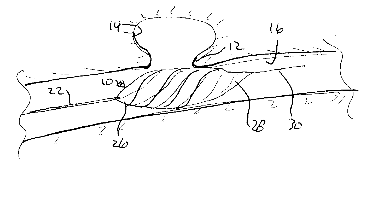
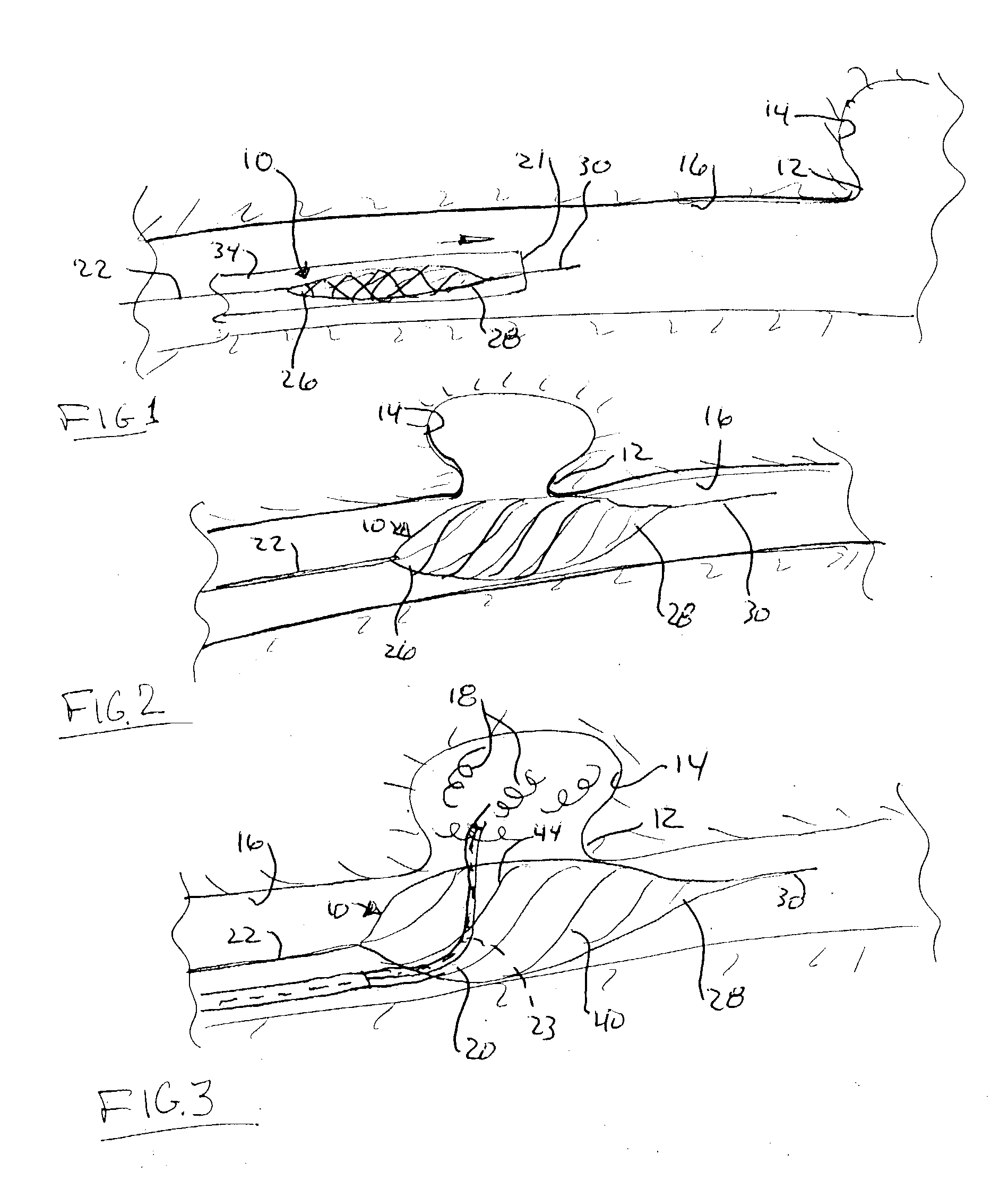
[0036] Referring now to the drawings in detail, and particularly to FIG. 1, there is shown the present invention which comprises a method of filling and buttressing an intracranial aneurysm. The method comprises the steps of transluminally positioning a buttress scaffold 10 from an initial unexpanded delivery diameter of for example about 0.018 to about 0.030 inches into an expanded diameter of for example about 2-6 mm across an opening 12 of an aneurysm 14 in an intracranial vessel 16 so as to block off and isolate that aneurysm cavity 14 in a side wall of that vessel 16, as shown in FIGS. 1, 2 and 3. Media such as embolitic agents 18, for example, coils, and or polymers may then be introduced by a further microcatheter 20, into that cavity 14 within the sidewall of the vessel 16, as represented in FIG. 3. The cavity 14 for our description of treatment purposes is of a bulbous shape having a neck portion 12.

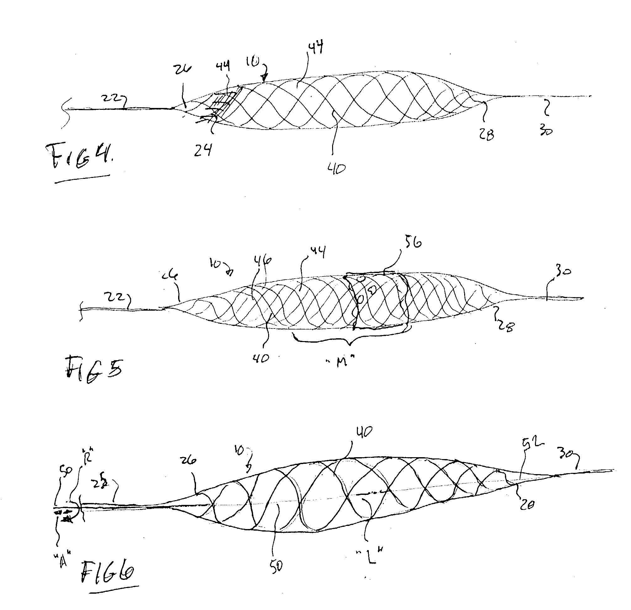
[0037] The buttress scaffold 10 is arranged on the distal end of an elonga...


PUM


Abstract

An aneurysm buttressing arrangement for covering an aneurysm opening in an intracranial aneurysm, for temporary placement thereadjacent, to prevent escape of embolitic agents from that aneurysm. The arrangement comprises an elongated delivery wire having a proximal end and a tracking distal end wire, a scaffold of expandable wires arranged proximal to and in spaced adjacent relationship to the distal end of the delivery wire, wherein the scaffold of wires has a tapered proximal end and a tapered distalmost end, the scaffold being expandable upon deployment from a delivery catheter, and collapsible for withdrawal into a delivery catheter, the tracking distal end wire extending distally from the scaffold about one-half to about ten centimeters.

Description

BACKGROUND OF THE INVENTION [0001] 1. Field of the Invention [0002] This invention relates to methodology and apparatus for the treatment of an aneurysm particularly intracranial aneurysms, and is based upon the provisional patent application Ser. No. 60 / 395,974 filed on 12 Jul. 2002, which provisional application is incorporated herein by reference in its entirety. [0003] 2. Prior Art [0004] The present invention relates to the treatment of vascular aneurysms, and, in particular, to methods and devices for filling aneurysms with an embolic or other material, while maintaining patency of the adjacent vessel. [0005] Various implantable medical devices have been developed for treating ailments in the vascular system. Vaso-occlusive devices have been used extensively in closing regions of the vascular system. These devices are especially useful in treating aneurysms. Vascular aneurysms are formed as a result of a weakening in the wall of an artery and subsequent ballooning of the arter...

Claims


Application Information

Patent Timeline
Patent Type & Authority Applications(United States)
IPC IPC(8): A61B17/00A61B17/12A61F2/06A61M29/00
CPCA61B17/12022A61B17/12118A61B17/12136A61B17/1214A61B2017/1205A61M29/02A61B17/12172A61B17/12186A61B2017/00867A61F2/966A61B17/12113
Inventor GUTERMAN, LEE R.LADUCA, PAUL A.LADUCA, ROBERT C.
Owner NIAGARA GORGE MEDICAL DEVICES
Why Eureka
Try Eureka