Jet flow generating apparatus, electronic apparatus, and jet flow generating method

a technology of jet flow and generating apparatus, which is applied in the direction of electrical apparatus casing/cabinet/drawer, positive-displacement liquid engine, and semiconductor/solid-state device details. it can solve the problems of difficult effective removal of heat, noise the bearing portion of the fan nose, so as to prevent the noise of the apparatus from generating, suppress the noise of the apparatus, and prevent the effect of nois

Inactive Publication Date: 2005-06-09
SONY CORP
View PDF15 Cites 78 Cited by
  • Summary
  • Abstract
  • Description
  • Claims
  • Application Information

AI Technical Summary

Benefits of technology

[0071] According to an embodiment of the present invention, the medium is a gas. The jet flow generating apparatus further comprises a vibrating member for vibrating the gas. The plurality of discharging means each has an opening through which the gas vibrated by the vibrating member is jetted outside the apparatus. The wave form adjusting means has control means for controlling the vibration of the vibrating member. Since the control means is configured to control the vibration of the vibrating member, the sound waves that are generated are offset and thereby the noise of the apparatus can be prevented from generating.
[0072] According to the present invention, when the distance of adjacent openings of at least one discharging means is denoted by d (m

Problems solved by technology

As the performance of PCs (Personal Computers) has been advanced, the calorific powers of heat generating members such as ICs (Integrated Circuits) have been adversely increased.
However, there is a problem that a thermal boundary layer of fin surface is generated on the downstream side of the heat radiation fins by the forced conversion of air by the fan, it is difficult to effectively take away the heat.
But, there is a problem that nose of a bearing portion

Method used


Image

  • Jet flow generating apparatus, electronic apparatus, and jet flow generating method
  • Jet flow generating apparatus, electronic apparatus, and jet flow generating method
  • Jet flow generating apparatus, electronic apparatus, and jet flow generating method

Examples


Embodiment Construction

[0129] The present invention relates to a jet flow generating apparatus that generates a jet flow and cools a heat generating member such as an electronic part with the generated jet flow, an electronic device that is equipped with the jet flow generating apparatus, and a jet flow generating method.

[0130] Next, with reference to the accompanying drawings, an embodiment of the present invention will be described.

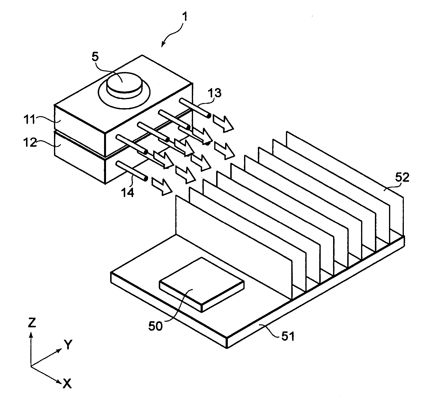
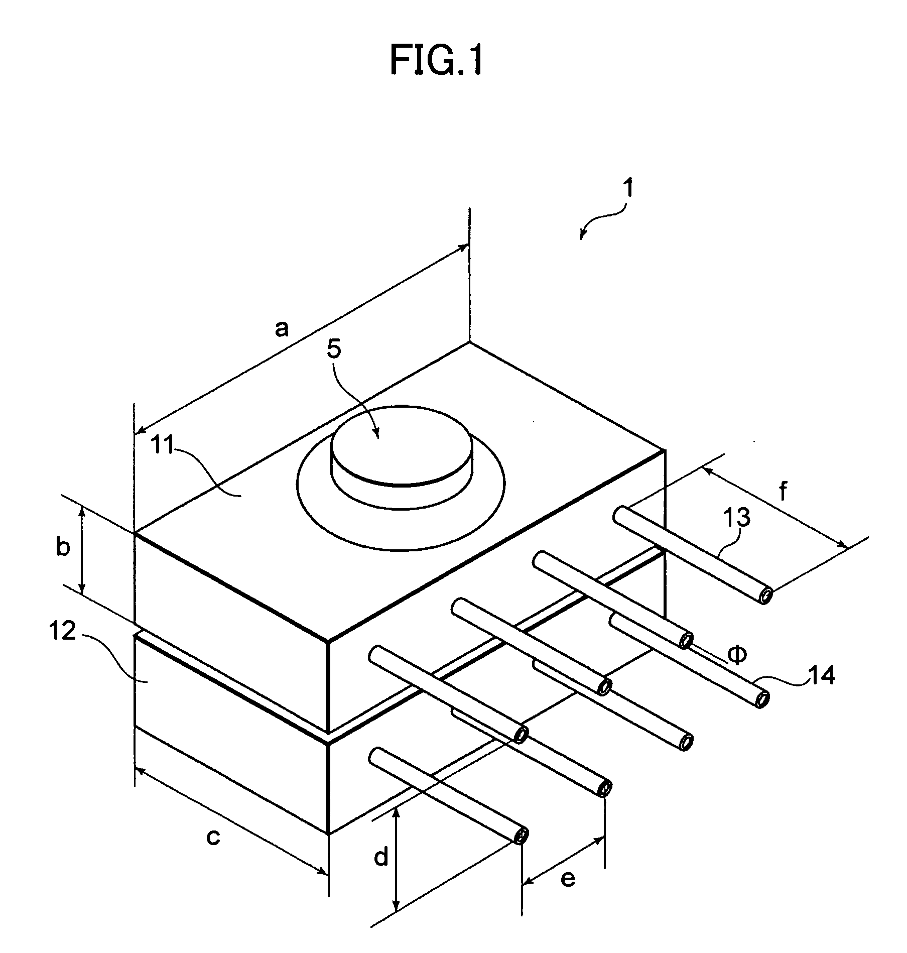
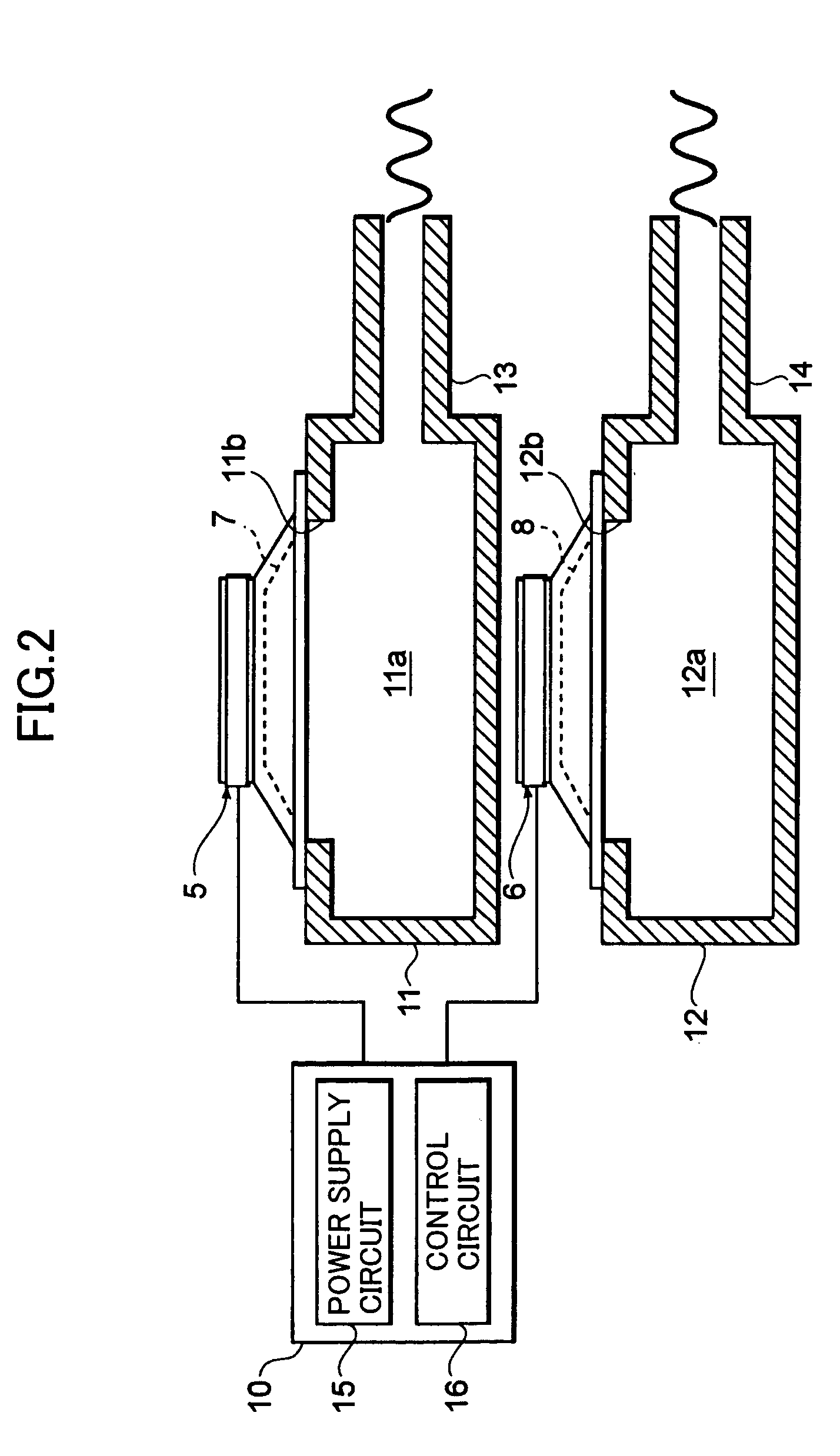
[0131]FIG. 1 is a perspective view showing a jet flow generating apparatus according to an embodiment of the present invention. FIG. 2 is a sectional view showing the jet flow generating apparatus.

[0132] A jet flow generating apparatus 1 has, for example, two independent casings 11 and 12. The casings 11 and 12 have vibrating mechanisms 5 and 6, respectively. The vibrating mechanisms 5 and 6 have vibration plates 7 and 8, respectively. The vibration plates 7 and 8 are composed of a soft film material, for example, PET (polyethylene terephthalate) film or the like. The vibr...


PUM


Abstract

A jet flow generating apparatus that suppresses noise as much as possible and effectively radiates the heat generated by a heat generating member, an electronic device that is equipped with the jet flow generating apparatus, and a jet flow generating method are provided. According to the present invention, a jet flow generating apparatus comprises a plurality of chambers each having an opening and each containing a coolant, a vibrating mechanism for vibrating the coolant contained in each of the plurality of chambers so as to discharge the coolant as a pulsating flow through the openings, and a control unit for controlling the vibration of the vibrating mechanism so that the sound waves generated by the coolant discharged from the plurality of chambers weaken each other.

Description

CROSS REFERENCES TO RELATED APPLICATIONS [0001] This application claims priority to Japanese Patent Document Nos. JP2003-374922 filed on Nov. 4, 2003, JP2004-035815 filed on Feb. 12, 2004, and JP2004-232581 filed on Aug. 9, 2004, the entire disclosures of which are incorporated herein by reference. BACKGROUND OF THE INVENTION [0002] The present invention relates to a jet flow generating apparatus that generates a jet flow and cools a heat generating member such as an electronic part with the generated jet flow, an electronic device that is equipped with the jet flow generating apparatus, and a jet flow generating method. [0003] As the performance of PCs (Personal Computers) has been advanced, the calorific powers of heat generating members such as ICs (Integrated Circuits) have been adversely increased. To solve such a problem, various heat radiating technologies have been proposed and / or practically used. As one of heat radiating methods, there is a method wherein heat radiating fi...

Claims


Application Information

Patent Timeline
IPC IPC(8): F04D33/00F04B45/04F04F7/00H05K7/20
CPCF04F7/00F04D33/00H05K7/20
Inventor MUKASA, TOMOHARUHORI, KAZUHITOISHIKAWA, HIROICHIYOKOMIZO, KANJINAKAYAMA, NORIKAZU
Owner SONY CORP
Why Eureka
Try Eureka