
Capping board with at least one sheet of electrically conductive material embedded therein

Active Publication Date: 2005-06-09
PULTRUSION TECHN
View PDF8 Cites 31 Cited by
  • Summary
  • Abstract
  • Description
  • Claims
  • Application Information

AI Technical Summary

Benefits of technology

[0021] It has now been discovered that when at least one sheet of conductive material is embedded inside a capping board in such a way that this sheet forms a seat for all the legs of the plates that are not to be in contact with a supply bar or, alternatively, this sheet forms a seat for all the legs of the plates that are to be connected to an electric source and thus acts as a contact bar, then one may reduce the above problem of wearing while simultaneously providing rapid and fast dissipation of the heat that may be generated by a short circuit. The embedded sheet marks it possible for the capping board to withstand the thermo mechanical strength required to resist to the heavy weight of the metal plates even in the presence of high temperature created by the short circuit.
[0024] Such an improvement allows fast dissipation of heat in the case of a short circuit. Such also allows better distribution of electric current density.

Problems solved by technology

If such has proved to be sufficient, there are still some problems with the existing systems using of capping boards with one or more supply bars placed on their top surfaces.
One of these problems is due to short circuits occurring during the hydrometallurgical operation of the electrolysis or electro-winning process.
Other problems are also due to poor repartition of the electric current density distribution.
Such may in time substantially decrease the lifetime of the capping board and causes short circuit.
Such deformation is unacceptable since it may generate short circuits that may propagate from one cell to another cell.
These short circuits may produce a refined metal with major impurity and defects that gives to the quality of the refined metal a poor quality to be rejected.

Method used


Image

  • Capping board with at least one sheet of electrically conductive material embedded therein
  • Capping board with at least one sheet of electrically conductive material embedded therein
  • Capping board with at least one sheet of electrically conductive material embedded therein

Examples


Embodiment Construction

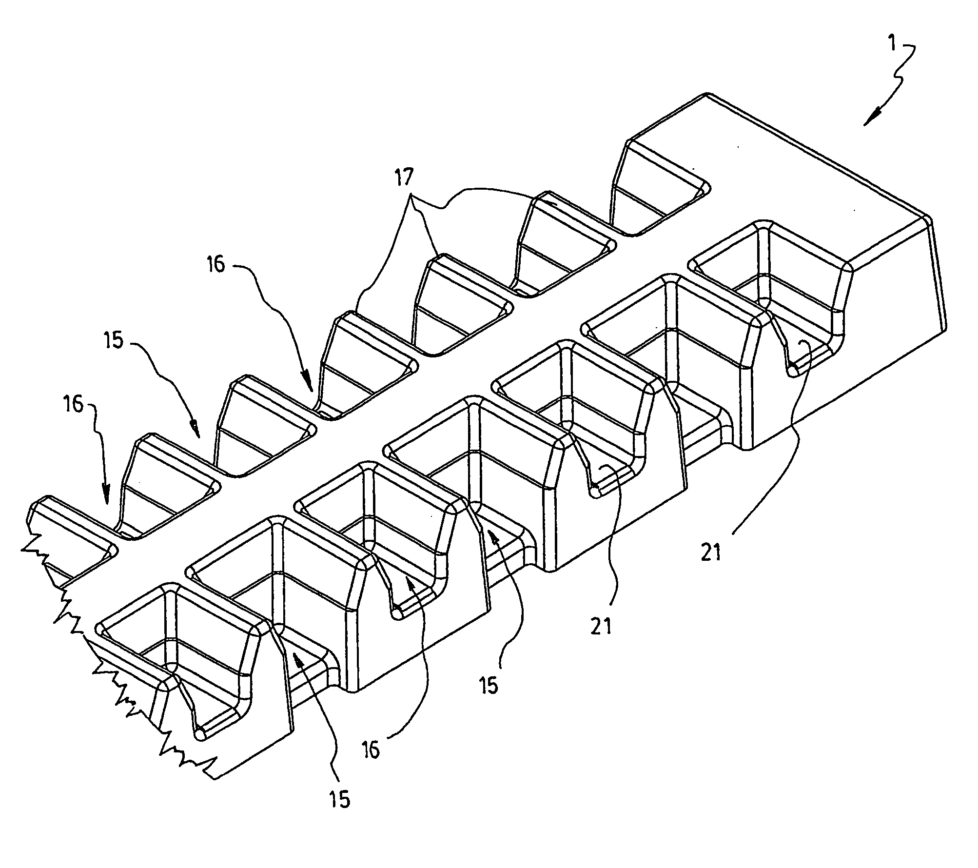
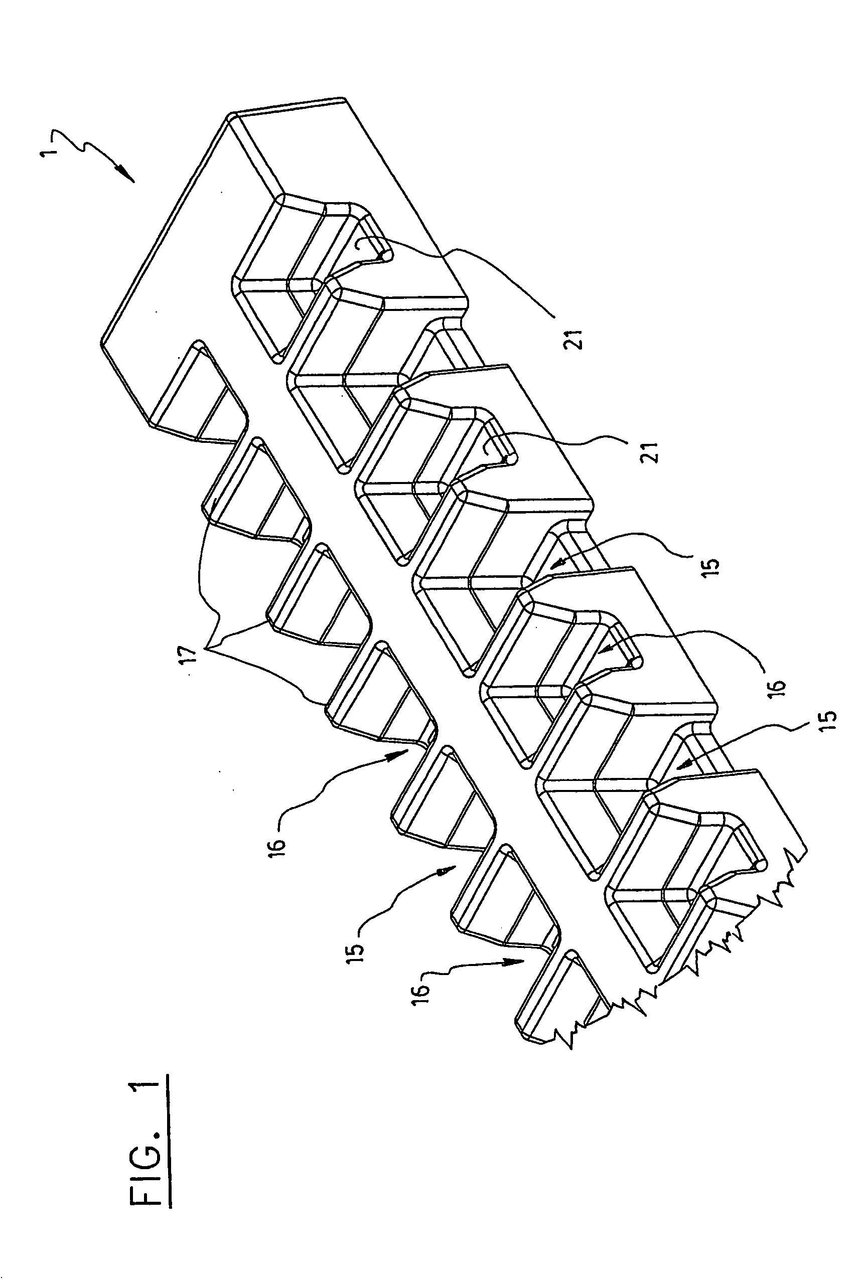
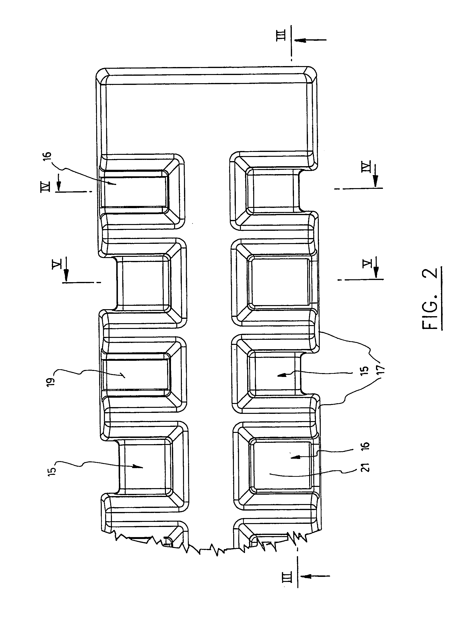
[0042] Like all the existing capping boards, the improved capping board according to the invention as shown in the accompanying drawings, is intended to be used as a support for electrodes in an electrolytic cell. More particularly, it is intended to be positioned on the top surface of a lateral sidewall of a cell on which electrodes are hanged, in order to position them in precise layout alternation while simultaneously protecting this top surface from shocks occurring when handling the electrodes and while avoiding damage caused by the heavy weight of the electrodes.

[0043] More specifically, the capping board 1 according to the first preferred embodiment of the invention as shown in FIGS. 1 to 7 is intended to be used for supporting anodes 3 and cathodes 5 within adjacent electrolytic cells 7, 9. This capping board 1 comprises a main body of a given length having a bottom surface 11 shaped fit onto a contact bar located on top of the upper edges of the two adjacent cells 7, 9 (se...


PUM

PropertyMeasurementUnit
Fractionaaaaaaaaaa
Fractionaaaaaaaaaa
Percent by massaaaaaaaaaa

Abstract

Disclosed is a capping board for use to support anodes and cathodes within adjacent electrolytic cells, which has a plurality of individual seats positioned in spaced apart relationship all along its length to receive and support hanging legs projecting from these anodes and cathodes. This capping board is improved in that it has at least one sheet or wire of electrically conductive material embedded therein. This sheet or wire extends over the length of the board and is shaped and positioned so that part of its extends externally within at least some of the seats so as to allow electrical contact of the legs of either the anodes or the cathodes and to allow fast dissipation of heat in the case of a short circuit.

Description

BACKGROUND OF THE INVENTION [0001] A) Field of the invention [0002] The present invention relates to a capping board of improved structure, which comprises at least one sheet of electrically conductive material embedded therein. [0003] B) Brief Description of the Prior Art [0004] In the hydrometallurgical industry, it is of common practice to refine metal by electrolysis in electrolytic cells especially designed for this purpose. The metals to be refined are usually conventional metals like copper, zinc, nickel or cadmium, or precious metals like silver, platinum or gold, and others. [0005] In the commonly used hydrometallurgical process, metal plates are used as anodes or cathodes or both. These metal plates weight several hundred pounds. Usually, the metal to be refined, or the metal used to carry the electric current, is in the form of plates of a given thickness, which are provided at their upper end with two laterally extending projections. Such projections facilitate gripping,...

Claims


Application Information

Patent Timeline
IPC IPC(8): C25B9/02C25C7/02C25D17/10
CPCC25C7/02
Inventor DUFRESNE, ROBERT P.
Owner PULTRUSION TECHN
Learn More