Heating method for a band-shaped body and heating apparatus for a band-shaped body

a heating apparatus and band-shaped technology, applied in the direction of drying machines with progressive movements, furnaces, photosensitive materials, etc., can solve the problems of requiring certain time and considerable waste, and achieve the effect of minimizing the loss of time, materials and products, and reducing the variation of product quality accompanying changes in drying and curing conditions

Inactive Publication Date: 2005-06-09
FUJIFILM HLDG CORP +1
View PDF8 Cites 80 Cited by
  • Summary
  • Abstract
  • Description
  • Claims
  • Application Information

AI Technical Summary

Benefits of technology

[0079] The invention provides a heating method and a heating apparatus for a band-shaped body in which: micro flaws are not generated; the temperature history of the band-shaped body can be made approximately constant, even

Problems solved by technology

When, however, the drying condition is changed, a certain time is required until the drying conditions become stable.
For this reason, during the interval from the

Method used


Image

  • Heating method for a band-shaped body and heating apparatus for a band-shaped body
  • Heating method for a band-shaped body and heating apparatus for a band-shaped body
  • Heating method for a band-shaped body and heating apparatus for a band-shaped body

Examples


first embodiment

[0098] A heating apparatus for a band-shaped body according to a first embodiment is explained below.

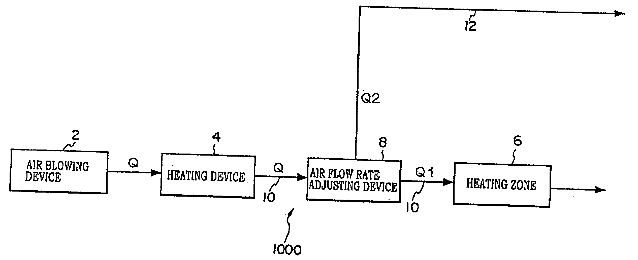
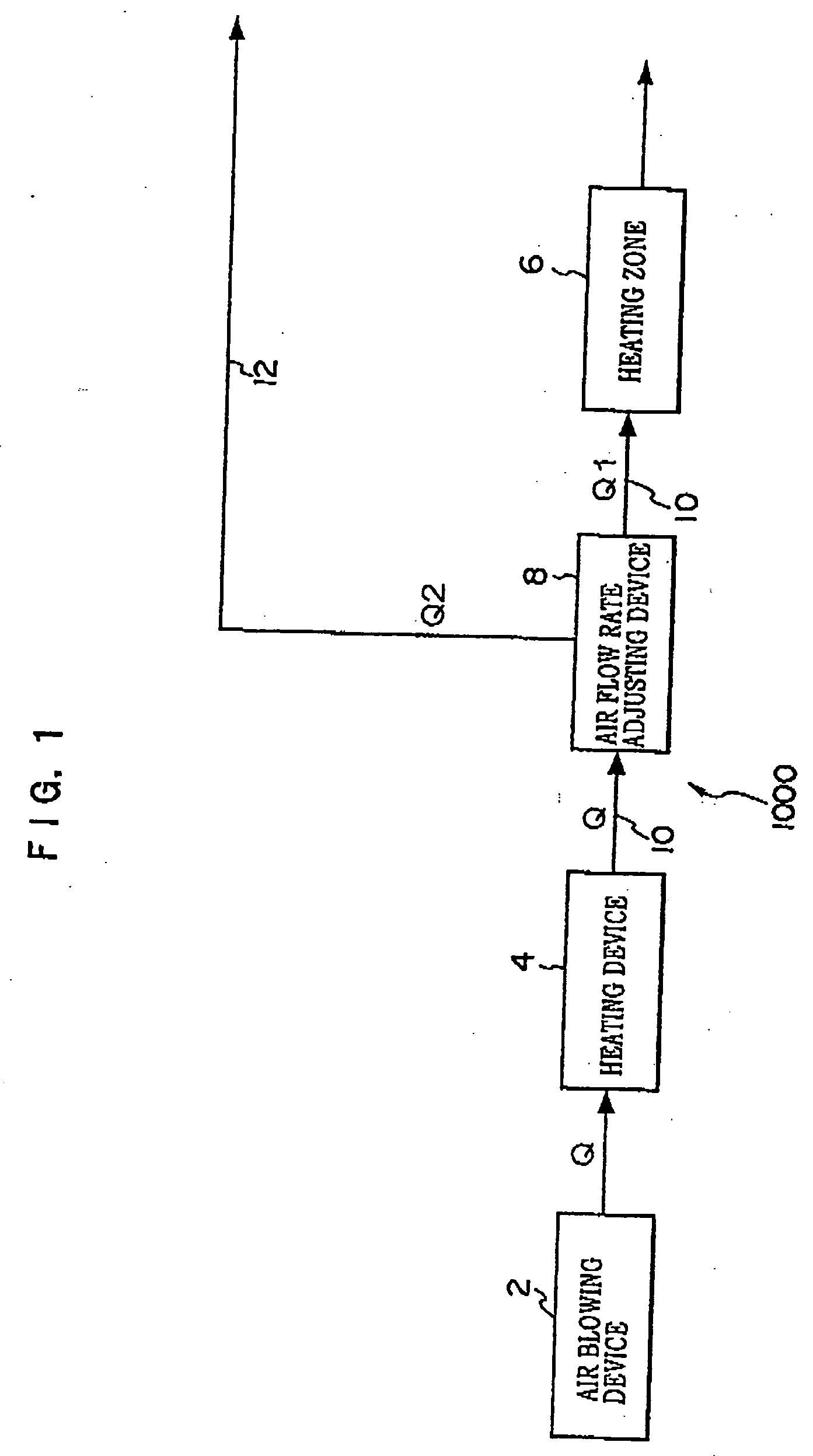
[0099] As shown in FIG. 1, the heating apparatus for a band-shaped body 1000 according to the first embodiment includes an air blowing device 2, a heating device 4, a heating zone 6, a heated air stream supply flow channel 10, an air flow rate adjusting device 8, and an excess air stream discharge flow channel 12. The air blowing device 2 generates an air stream with a constant air flow rate Q. The heating device 4 heats the air stream generated by the air blowing device 2. The heated air stream generated by the heating device 4 is introduced into the heating zone 6. The heated air stream supply flow channel 10 is used for introducing the heated air stream from the heating device 4 into the heating zone 6. The air flow rate adjusting device 8 is provided on the heated air stream supply flow channel 10, and divides the heated air stream with air flow rate Q, generated by the air blow...

second embodiment

[0110] The heating apparatus for a band-shaped body according to a second embodiment is explained below.

[0111] As shown in FIG. 5, the heating apparatus for a band-shaped body 1002 according to the second embodiment is provided with a return flow channel 14 for returning a discharged air stream from the heating zone 6 to a point between the air blowing device 2 and the heating device 4.

[0112] The air flow rate adjusting device 18 is set on the return flow channel 14. This device divides the discharged air stream from the heating zone 6 into a return air stream to the heating device 2 and a discharged air stream discharged out of the band-shaped heating apparatus 1002. The excess air stream discharge flow channel 20 for discharging the discharged air stream out of the system is provided to the air flow rate adjusting device 18.

[0113] The air flow rate adjusting device 8 divides the heated air stream introduced from the heating device into: an introduced air stream, to be introduce...

third embodiment

[0122] The heating apparatus for a band-shaped body 1004 according to a third embodiment has a heated air stream generating device A and a heated air stream generating device B as shown in FIG. 7.

[0123] The heated air stream generating device A includes an air blowing device 2A and a heating device 4A which are similar to the air blowing device 2 and the heating device 4. The heated air stream generating device B includes an air blowing device 2B and a heating device 4B similar to the air blowing device 2A and the heating device 4A in the heated air stream generating device A.

[0124] The heated air stream supply flow channel 10A and the heated air stream supply flow channel 10B are set between the heated air stream generating device A and the heating zone 6 and between the heated air stream generating device B and the heating zone 6, respectively. The heating air stream supply flow channels 10A and 10B join together just before the heating zone 6 so as to form the heated air stream...


PUM


Abstract

A heating method for a band-shaped body transported in a constant conveying direction in a heating zone so as to heat it, comprises: detecting whether or not a portion of the band-shaped body is passing through the heating zone, at which portion at least one of width and thickness of the band-shaped body changes; before detecting the portion pass into the heating zone, setting a first supplied heat quantity based on dimensions of the first band-shaped body on a downstream side of the portion in the conveying direction, and supplying heat with the first supplied quantity to the band-shaped body in the heating zone; and after detecting that the portion has passed into the heating zone, setting a second supplied heat quantity based on dimensions of the second band-shaped body on an upstream side of the portion relative to the conveying direction, and supplying heat with the second supplied quantity to the band-shaped body in the heating zone, so as to adjust a temperature history of the band-shaped body so that the temperature history is approximately uniform on both upstream and downstream sides of the portion.

Description

CROSS-REFERENCE TO RELATED APPLICATION [0001] This application claims priority under 35 USC 119 from Japanese Patent Application No. 2003-404242, the disclosure of which is incorporated by reference herein.BACKGROUND OF THE INVENTION [0002] 1. Field of the Invention [0003] The present invention relates to a heating method and a heating apparatus for a band-shaped body. The invention particularly relates to a heating method and heating apparatus that heat and dry a coating liquid applied to a band-shaped body in such a way as to enable a temperature history of the band-shaped body to be practically uniform on both upstream and downstream sides of a joint portion passing through, at which joint portion two band-shaped bodies with at least one of different widths or different thicknesses are joined. [0004] 2. Description of the Related Art [0005] Planographic printing plates, silver salt films such as photographic films and cinefilms, photographic paper, and magnetic recording material...

Claims


Application Information

Patent Timeline
IPC IPC(8): B05C9/14G03F7/00B05D3/02B05D7/00F26B13/00G03D13/00H05B3/58
CPCG03D13/002
Inventor KAMITANI, KIYOSHIHAYASHI, KENJI
Owner FUJIFILM HLDG CORP
Why Eureka
Try Eureka