Optical element and method of molding the same

a technology of optical elements and molds, applied in the field of optical elements, can solve the problems of small ghosts seriously affecting function and accuracy, affecting the surface of sensor image forming, and not being able to completely eliminate ghosts, so as to facilitate the mold of optical elements capable of preventing ghosts, without reducing the internal diameter of stoppers

Active Publication Date: 2005-06-09
FUJI PHOTO OPTICAL CO LTD
View PDF7 Cites 23 Cited by
  • Summary
  • Abstract
  • Description
  • Claims
  • Application Information

AI Technical Summary

Benefits of technology

[0011] It is an object of the present invention to provide an optical element which can prevent a ghost without reducing the internal diameter of a stopper.
[0012] In order to attain the object, the present invention provides an optical element comprising an optical function surface of high surface accuracy and a flange formed around the surface, the optical function surface having an optical surface diameter somewhat larger than the effective diameter in order to secure high surface accuracy for the effective diameter, wherein a molding die has a parting diameter larger than the optical surface diameter and a parting position is disposed outside the optical surface diameter.
[0013] According to the optical element of the present invention, it is possible to prevent a ghost without reducing the internal diameter of a stopper, so that a peripheral luminous flux is not reduced in light quantity and the corners of an image are not darkened. Further, it is possible to obtain an optical element capable of preventing a ghost without special after treatment and readily mold the optical element capable of preventing a ghost.

Problems solved by technology

In the sensor lens using the optical element composed of the optical function surface of high surface accuracy and a flange formed around the surface, the sensor image-forming surface is adversely affected by the scattering of light having been incident outside the optical function surface of the optical element, resulting in a ghost or flare.
However, even in the sensor lens comprising the stopper 109 for interrupting scattered light caused by light having been incident outside the optical function surface, e.g., on the flange, it is not possible to completely eliminate a ghost.
Further, as compact digital cameras have increased in functionality and accuracy, just a small ghost seriously affects the function and accuracy.

Method used


Image

  • Optical element and method of molding the same
  • Optical element and method of molding the same
  • Optical element and method of molding the same

Examples


Embodiment Construction

[0023] The following will describe an embodiment of the present invention in accordance with the accompanying drawings.

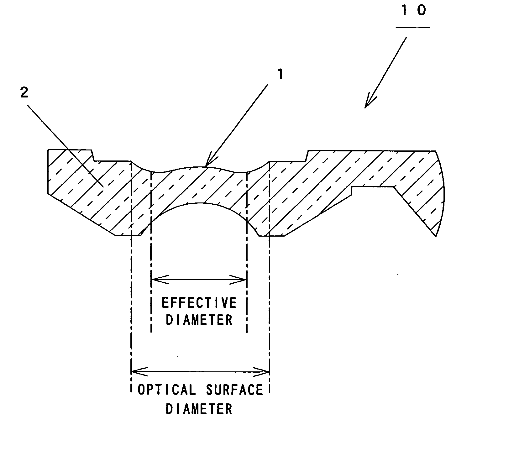
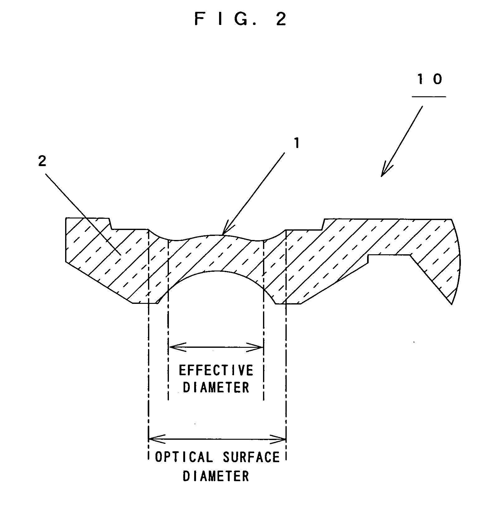
[0024] As shown in FIG. 2, in an optical element 10 constituted of an optical function surface 1 of high surface accuracy and a flange 2 formed around the surface 1, the optical function surface 1 has a somewhat larger optical surface diameter than an effective diameter in order to secure high surface accuracy for an effective diameter.

[0025] That is, in the molding of the optical element 10, the optical function surface 1 is formed with an optical surface diameter somewhat larger than the effective diameter, so that accuracy for the effective diameter is secured. In order to secure accuracy for the effective diameter, it is enough to set an optical surface diameter which is about 0.1 mm larger than the effective diameter (about 2% relative to the effective diameter).

[0026]FIG. 3 shows a molding die 20 used for molding the optical element 10 having the optical fu...


PUM

PropertyMeasurementUnit
diameteraaaaaaaaaa
diameteraaaaaaaaaa
surface accuracyaaaaaaaaaa

Abstract

The present invention provides an optical element capable of preventing a ghost in the use for a sensor such as a CCD or CMOS. In the optical element including an optical function surface of high surface accuracy and a flange formed around the surface, the optical function surface having an optical surface diameter somewhat larger than an effective diameter in order to secure high surface accuracy for the effective diameter, a parting diameter of a molding die is made larger than the optical surface diameter and a parting position is disposed outside the optical surface diameter.

Description

BACKGROUND OF THE INVENTION [0001] 1. Field of the Invention [0002] The present invention relates to an optical element used for a sensor such as a CCD and CMOS, and particularly relates to an optical element and a method of molding the same whereby a ghost is prevented. [0003] 2. Description of the Related Art [0004] In recent years, as compact digital cameras mounted in mobile telephones or the like have increased in functionality and accuracy, higher accuracy is demanded of small sensor lenses used for the digital cameras. [0005]FIG. 1 shows the configuration of a lens using a sensor (including a CCD and CMOS) of a compact digital camera mounted in a mobile telephone or the like. [0006] In a sensor lens 100 of FIG. 1, first to third optical elements 101 to 103 are fixed to a lens-barrel 105 with adhesive 104 and the optical elements with the lens-barrel are mounted in a mounting holder 106 which has a cover glass 107. In the sensor lens 100, light incident from a condensing port ...

Claims


Application Information

Patent Timeline
Patent Type & Authority Applications(United States)
IPC IPC(8): C03B11/08G02B7/02G02B6/32G02B9/16G02B13/00G02B27/00
CPCG02B6/32G02B27/0018G02B13/0035G02B9/16Y10S425/808Y10S385/901
Inventor ITO, TAKASHI
Owner FUJI PHOTO OPTICAL CO LTD
Why Eureka
Try Eureka