Method of removing mismatch bound polynucleotides

Inactive Publication Date: 2005-06-09
FUJIFILM HLDG CORP +1
View PDF10 Cites 14 Cited by
  • Summary
  • Abstract
  • Description
  • Claims
  • Application Information

AI Technical Summary

Benefits of technology

[0029] With the method of removing a mismatch bound polynucleotide in accordance with the present invention, after the labeled polynucleotide, which has been labeled with the labeling substance, has been subjected to the hybridization with the plurality of the oligonucleotide probes, which have been fixed respectively to the plurality of the regions on the supporting material, the restriction enzyme is caused to act upon the single-stranded moiety of the labeled polynucleotide, which moiety has failed to form the double strand with each of the plurality of the oligonucleotide probes having been respectively fixed to the plurality of the regions on the supporting material. The restriction enzyme is capable of decomposing the single-stranded polynucleotide from the terminal of the labeled polynucleotide. The single-stranded moiety of the labeled polynucleotide is thereby separated from the double strand, which has been formed by the labeled polynucleotide and each of the oligonucleotide probes. A nucleot

Problems solved by technology

However, it is not always possible to perform the reaction under the conditions optimum for each of the probe DNA's, which have been fixed respectively to the regions having been located at a high density.
The target DNA, which has undergone the mismatch binding, causes noise to occur at the time of signal detection and adversely affects a detection accuracy.
Therefore, the cDNA micro array has a high possibility that the probe DNA's on the cDNA micro array will undergo the mismatch binding.
However, in both the cases of the oligonucleotide array and the synthetic oligo array, it is not always possible to design such that the mismatch binding does not occur.
Particularly, in cases where analysis is to be made with respect to a long gene, such as a cDNA, it is almost impossible to design such that the mismatch binding does not occur.
Specifically, under conditions of temperatures lower than the Tm value, background noise due to the mismatch binding increases.
Also, under conditions of temperatures higher than the Tm v

Method used


Image

  • Method of removing mismatch bound polynucleotides
  • Method of removing mismatch bound polynucleotides

Examples


Embodiment Construction

[0032] The present invention will hereinbelow be described in further detail with reference to the accompanying drawings.

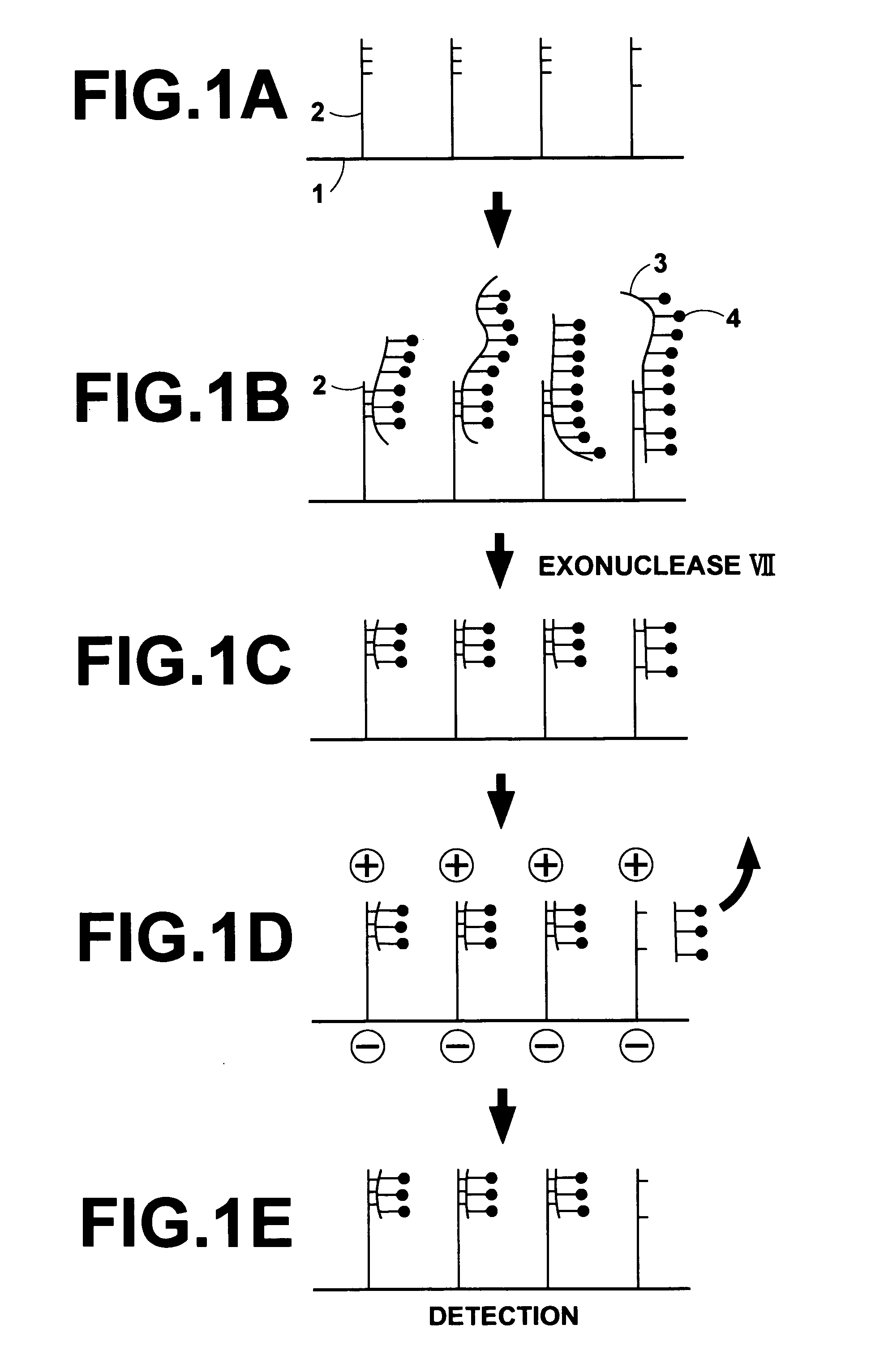
[0033] An embodiment of the method of removing a mismatch bound polynucleotide in accordance with the present invention, wherein a DNA array comprising a supporting material and a plurality of oligo DNA probes having been fixed respectively to a plurality of regions on the supporting material is utilized, will be described hereinbelow. FIGS. 1A to 1E are explanatory views showing how a mismatch bound DNA is removed with an embodiment of the method of removing a mismatch bound polynucleotide in accordance with the present invention.

[0034] Firstly, a surface of a membrane filter 1 acting as a supporting material is processed such that carboxyl groups (COOH) or aldehyde groups (COH) are exposed from the surface of the membrane filter 1 to the exterior. Also, an amino group (NH2) is introduced into a 5′-terminal of each of synthetic oligo DNA's acting as DNA probes ...


PUM

PropertyMeasurementUnit
Electric potential / voltageaaaaaaaaaa
Luminescenceaaaaaaaaaa

Abstract

A labeled polynucleotide is subjected to hybridization with oligonucleotide probes fixed respectively to regions on a supporting material. With a restriction enzyme, a single-stranded moiety of the labeled polynucleotide having failed to form a double strand with each probe is separated from a double strand having been formed by the labeled polynucleotide and each probe. Thereafter, an electrode is located at a surface of each region on the supporting material, and a voltage is applied to the electrode. The labeled polynucleotide, which has undergone a mismatch binding with a certain oligonucleotide probe, is thus separated from the corresponding region on the supporting material.

Description

BACKGROUND OF THE INVENTION [0001] 1. Field of the Invention [0002] This invention relates to a method of removing a mismatch bound polynucleotide from a biochemical analysis micro array used for detection, analysis, or the like, of a specific sequence contained in a polynucleotide, such as a DNA. [0003] 2. Description of the Related Art [0004] DNA micro arrays are expected to be applied to a wide range of fields of life science, such as monitoring of genetic expression, determination of base sequences of genes, analysis of gene polymorphism (SNP), analysis of gene amplification or deletion at cancered parts, classification of diseases, such as cancers, prediction of drug response characteristics, and searching of disease genes. [0005] Principles of assay techniques utilizing DNA micro arrays are based upon detection of nucleic acids through hybridization. Specifically, various different probe DNA's are arrayed at a high density at a plurality of regions of a surface of a supporting...

Claims


Application Information

Patent Timeline
IPC IPC(8): C12P19/34C12Q1/68C12N15/09
CPCC12Q1/6832C12Q1/6837C12Q2565/607C12Q2521/325
Inventor TSUCHIYA, TORU
Owner FUJIFILM HLDG CORP
Why Eureka
Try Eureka