Engine fuel supply control device

Inactive Publication Date: 2005-06-09
NISSAN MOTOR CO LTD
View PDF7 Cites 37 Cited by
  • Summary
  • Abstract
  • Description
  • Claims
  • Application Information

AI Technical Summary

Benefits of technology

[0017] In addition, with a vehicle equipped with a manual transmission, the engine speed must be lowered to the optimal level during an upshift, and particularly in order to improve upshift feel. In recent years there has been a tendency for intake collectors to be made larger in order to raise engine output and efficiency, and the delay time of fuel cut-off has been getting longer. Thus, in the prior art discussed above, the decrease in engine speed was even slower during an upshift, which prevented quick upshifts and resulted in upshift shock.
[0018] The present invention was conceived in an effort to solve or lessen these problems. Thus, one object of the present invention is to eliminate the problems caused by a cut-in delay during shifting so as to minimize the jerking sensation that acc

Problems solved by technology

It has been discovered that the following problems have been encountered with the above-mentioned cut-in delays in which a specific delay time is merely provided during fuel cut-off.
These problems are particularly present in vehicles equipped with a manual transmission.
During an upshift, a long delay time is maintained until a neutral range is entered after clutch disengagement, and during this time the drop-off in engine speed is slow, which means that the above problems cannot be completely avoided.
However, during shifting, and particularly during an upshift in which a shift to a higher gear is made, if the supply of fuel continues until a specific delay time has elapsed even after the accelerator pedal has fully returned, then the drop-off in engine speed is slower, and in some cases disengagement of the clutch can even result in revving of the engine.
Acc

Method used


Image

  • Engine fuel supply control device
  • Engine fuel supply control device
  • Engine fuel supply control device

Examples


Example

First Embodiment

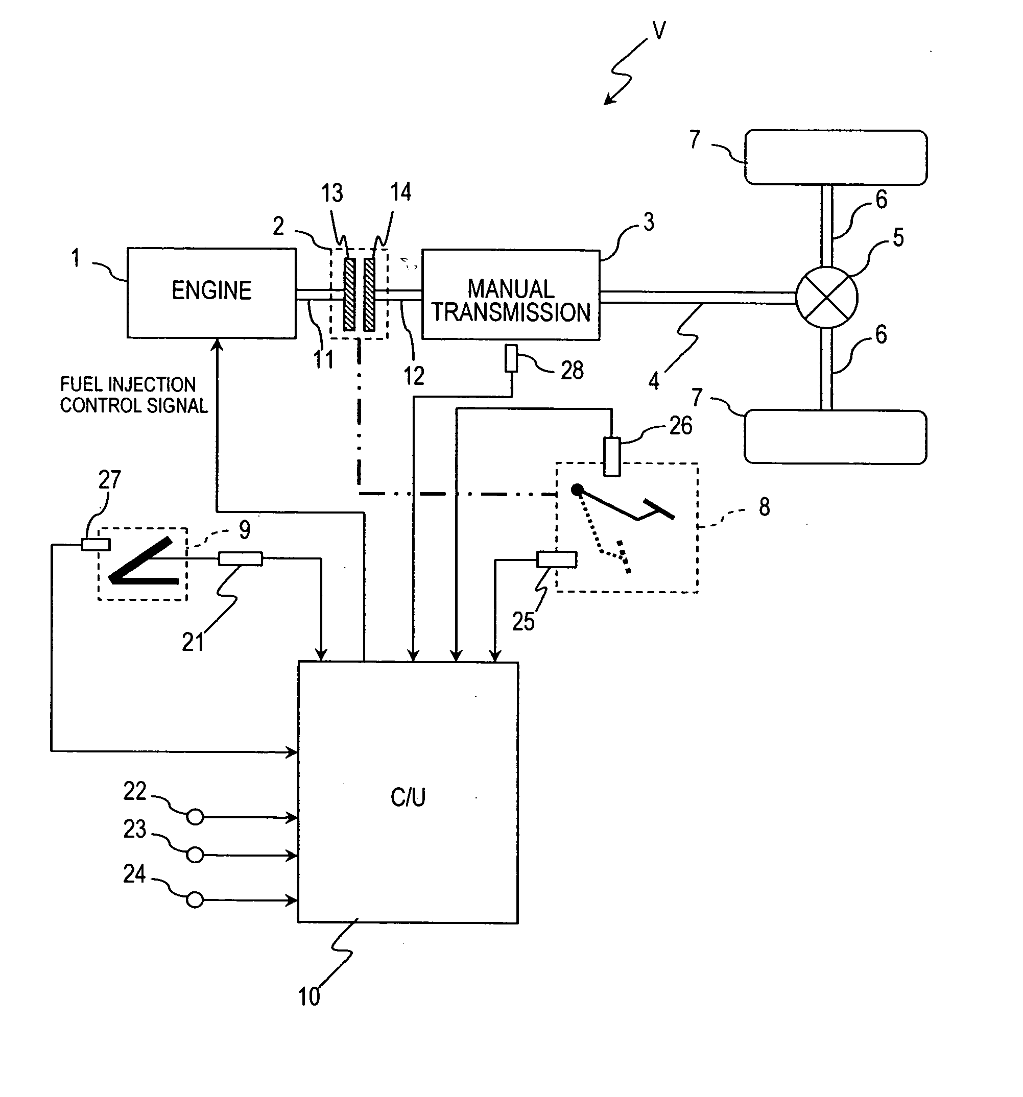
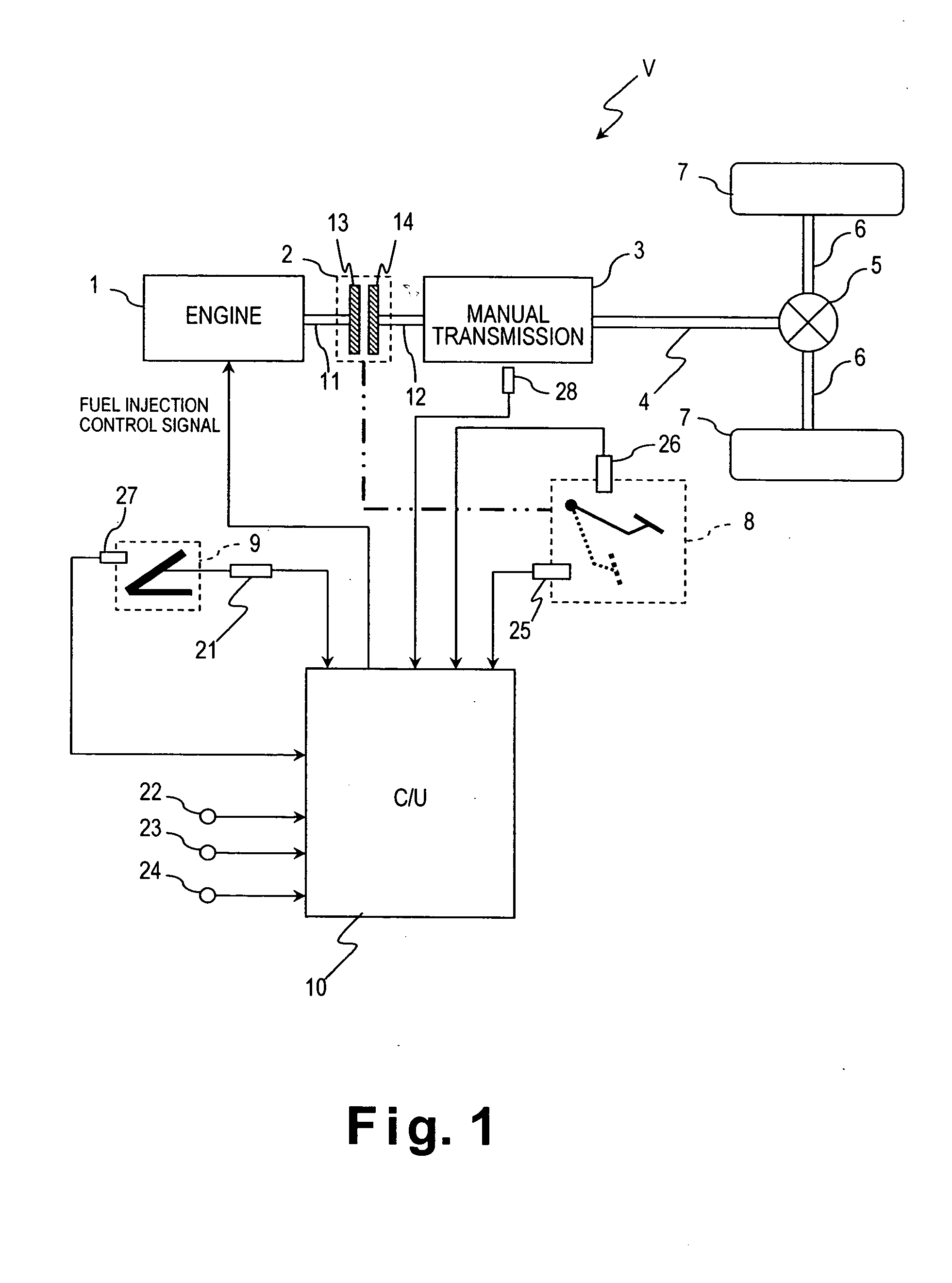
[0044] Referring initially to FIGS. 1-4, a vehicle V is schematically illustrated that is equipped with an engine fuel supply control device in accordance with a first embodiment of the present invention. FIG. 1 illustrates the configuration of the drive system of pertaining to an embodiment of the present invention. This vehicle V has a drive train that includes an engine 1, a clutch 2, a manual transmission 3, a propeller shaft 4, a differential 5 and a pair of wheel drive shafts 6. These components of the drive train are relatively conventional components, and thus, these parts will not be discussed or illustrated in detail herein. The wheel drive shafts 6 are coupled to a pair of drive wheels 7 in a conventional manner to rotate the drive wheels 7. The clutch 2 is engaged or disengaged according to the position of a clutch pedal 8 that is manually depressed by the driver's foot. The rotational speed of the engine 1 is manually controlled by an accelerator pedal ...

Example

Second Embodiment

[0079] Referring now to FIG. 5, a modified fuel injection quantity calculation routine is illustrated that is executed by the control unit 10 of the vehicle V that is equipped as shown in FIG. 1. In view of the similarity between the first and second embodiments, the parts or steps of the second embodiment that are identical to the parts or steps of the first embodiment will be given the same reference numerals. Moreover, the descriptions of the parts or steps of the second embodiment that are identical to the parts or steps of the first embodiment may be omitted for the sake of brevity. In other words, unless otherwise specified, the processing executed by the control unit 10 in the second embodiment is the same as the first embodiment. Thus, the modified processing will now be discussed.

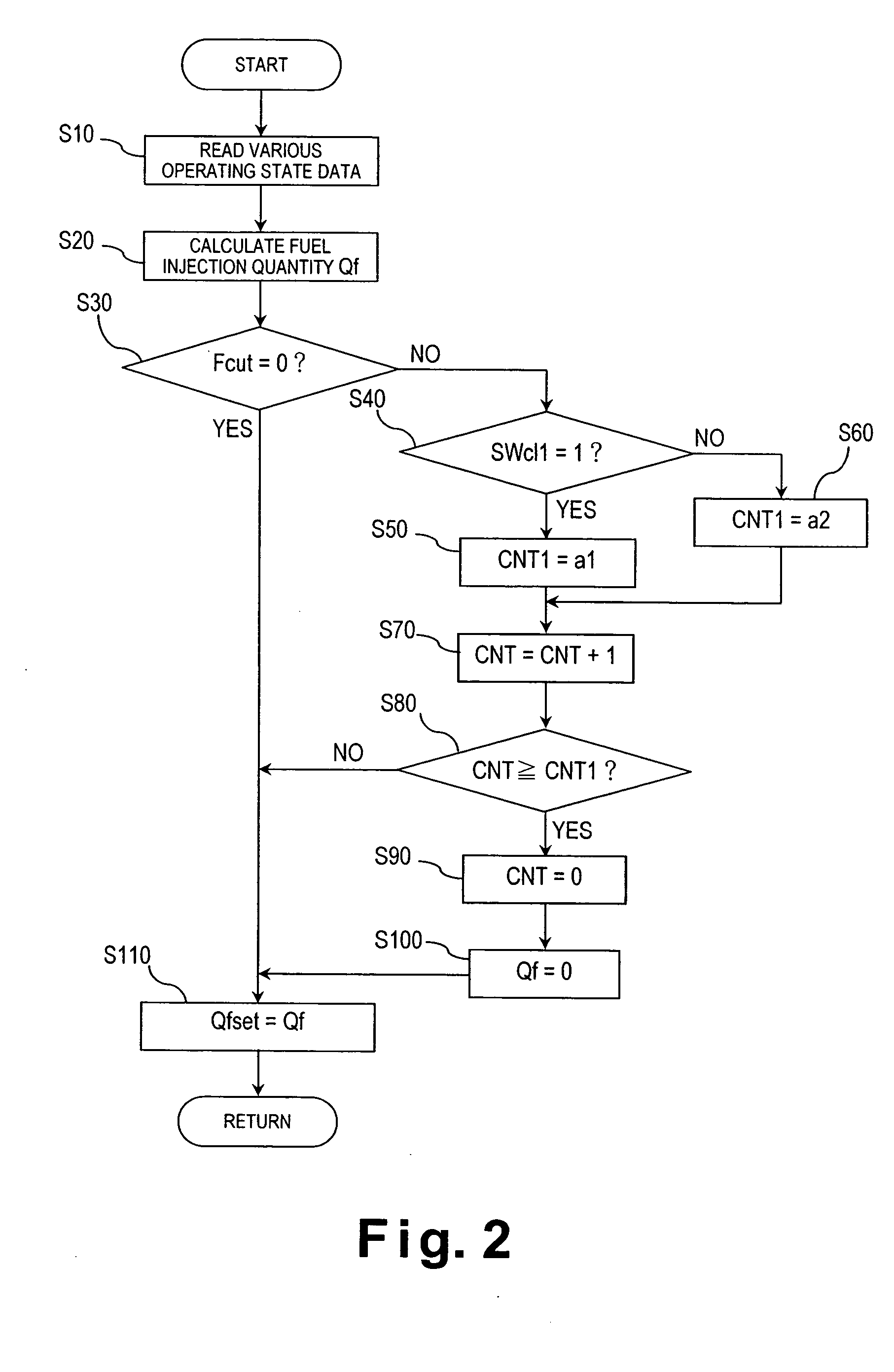
[0080]FIG. 5 is a flowchart illustrating the fuel injection quantity calculation routine when the supply of fuel is stopped as soon as the clutch 2 is disengaged. This routine is...

Example

Third Embodiment

[0085] Referring now to FIGS. 6-8, further modified processing executed by the control unit 10 will be discussed in accordance with a third embodiment of the present invention. This third embodiment is carried out by the control unit 10 of the vehicle V that is equipped as shown in FIG. 1. In view of the similarity between the first and third embodiments, the parts or steps of the third embodiment that are identical to the parts or steps of the first embodiment will be given the same reference numerals. Moreover, the descriptions of the parts or steps of the third embodiment that are identical to the parts or steps of the first embodiment may be omitted for the sake of brevity. In other words, unless otherwise specified, the processing executed by the control unit 10 in the third embodiment is the same as the first embodiment. Thus, the modified processing will now be discussed.

[0086] With the third embodiment of the present invention, the engine control unit 10 co...


PUM


Abstract

An engine fuel supply control device is configured to stop supplying fuel to an engine when specific fuel cut-off condition has been met. The timing of the fuel cut-off is delayed depending on an operating state of the vehicle. Preferably, the engine fuel supply control device has an operating state detection section that detects an operating condition (e.g., a clutch position or a shifting operation), and a fuel supply stoppage section that stops supplying fuel to the engine when a specific delay time has elapsed since the specific fuel cut-off condition was met. Preferably, the fuel supply stoppage section selectively sets the specific delay time to a different delay time depending upon the detected operating condition detection, e.g., a first delay time is set if either the clutch is detected as disengaged or a shifting operation is detected as being in progress, otherwise a different delay time is set.

Description

BACKGROUND OF THE INVENTION [0001] 1. Field of the Invention [0002] The present invention generally relates to a fuel supply control device for an engine. More specifically, the present invention relates to an engine fuel supply control device that stops the supply of fuel (performs fuel cut-off) after a specific delay time has elapsed since a specific fuel cut-off condition was met. [0003] 2. Background Information [0004] Fuel cut-off in which the supply of fuel is stopped when a specific fuel cut-off condition has been met, such as whether the accelerator pedal has fully returned, has been performed in the past in order to prevent the air-fuel mixture from being too rich during deceleration and to reduce fuel consumption. One commonly known method of a fuel cut-off using a cut-in delay is disclosed in Japanese Patent No. 2,605,755 (p. 3, column block, lines 6-15). In this method, after a specific fuel cut-off condition has been met, the supply of fuel is not stopped right away, bu...

Claims


Application Information

Patent Timeline
IPC IPC(8): F02D41/02F02D41/12
CPCF02D41/022F02D41/023Y10T477/675Y10T477/679F02D41/123
Inventor IRIYAMA, MASAHIRO
Owner NISSAN MOTOR CO LTD
Why Eureka
Try Eureka