Automatic transmission control system with shift lever position sensor

a technology of automatic transmission control and shift lever, which is applied in the direction of gearing control, gearing element, belt/chain/gearing, etc., can solve the problems of determining the failure of the inhibitor switch, the shift lever may be determined in error, and the output of error signals

Inactive Publication Date: 2005-06-16
DENSO CORP
View PDF2 Cites 60 Cited by
  • Summary
  • Abstract
  • Description
  • Claims
  • Application Information

AI Technical Summary

Benefits of technology

[0038] Each of the signals produced by the lever position sensor may carry a code made up of binary values. All of the binary values are designed to be active level values when the gear shift lever is placed in the drive position. This prevents the gear shift lever from being determined in error to be in the reverse position when it is actually placed between the neutral and drive position, which causes back-up lamps of the vehicle to be turned on.
[0039] A failure determining circuit may further be provided which works to monitor a failure in operation of the lever position sensor. Each of the signals produced by the lever position sensor carries

Problems solved by technology

The above type of inhibitor switch has the problem in that if a failure such as a wire disconnection or a short circuit occurs in any of the contacts S1 to S4, an error signal is outputted.
The above type of inhibitor switch, however, has the drawback in that if a pattern of a combination of outputs of the switches S1 to S4 matches any one of those as representing the P, R, N, and D position of the gear shift lever correctly, a difficulty is encounter

Method used


Image

  • Automatic transmission control system with shift lever position sensor
  • Automatic transmission control system with shift lever position sensor
  • Automatic transmission control system with shift lever position sensor

Examples


second embodiment

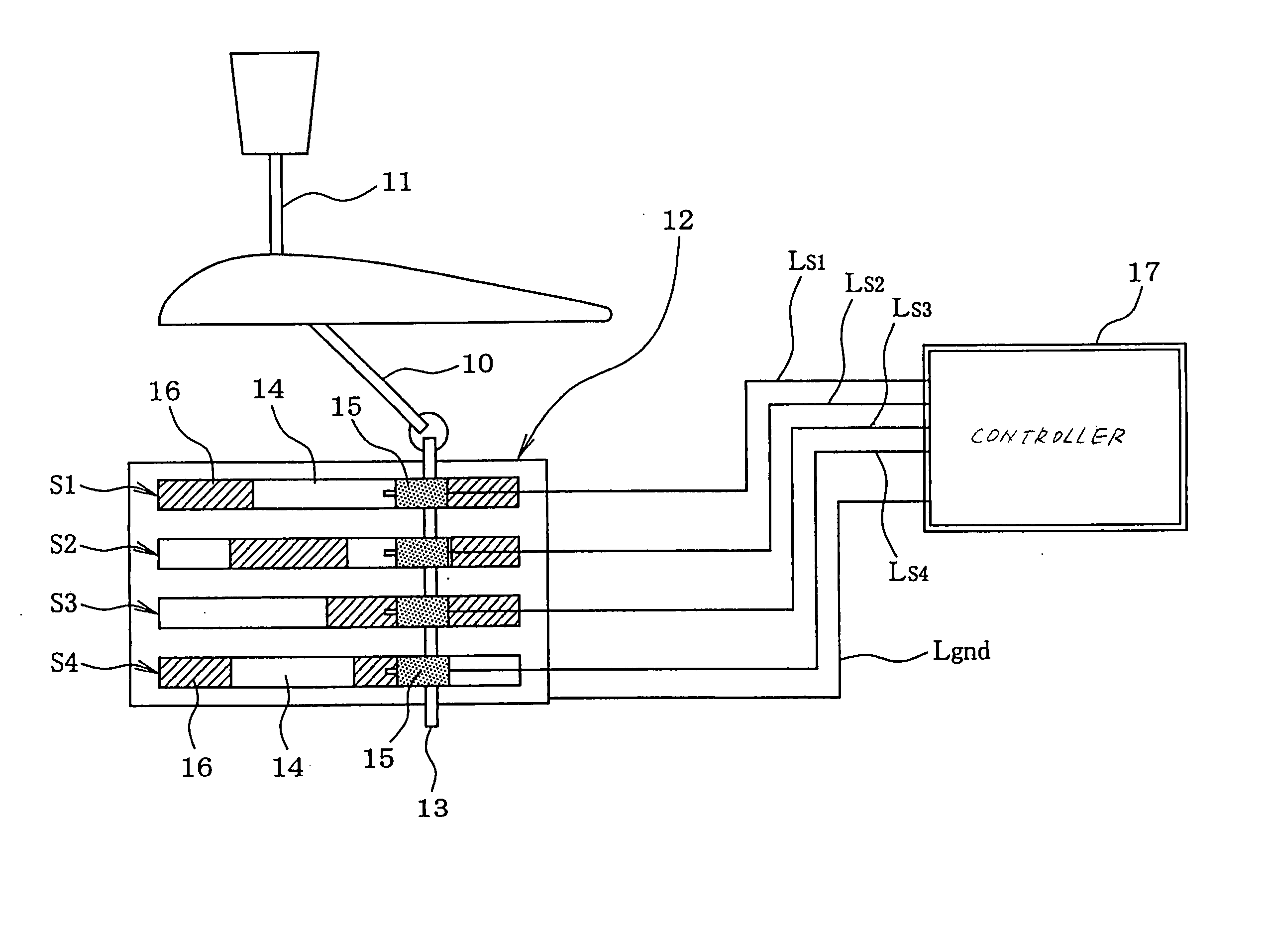
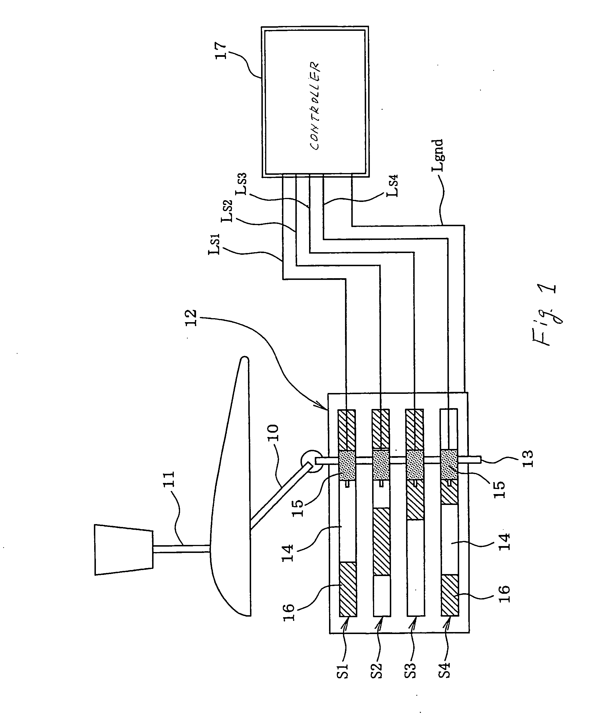
[0145]FIG. 8 shows an automatic transmission control system according to the invention.

[0146] The automatic transmission 110, as referred to this embodiment, is of a four-speed type which includes, as clearly shown in FIG. 9, a torque converter 120 and a hydraulic transmission gearbox 150. The torque converter 120 has an input shaft 130 joined to an output shaft of an automotive engine (not shown) and an output shaft 140 jointed to the hydraulic transmission gearbox 150. The torque converter 12 has installed therein a pump impeller 31 (i.e., a fluid coupling), turbine runner 32, and a stator 33 disposed between the pump impeller 31 and the turbine runner 32. The pump impeller 31 faces the turbine runner 32 and connects with the input shaft 130 of the torque converter 120. The turbine runner 32 connects with the output shaft 140 of the torque converter 120. The stator 33 works to rectify the torque converter oil.

[0147] The torque converter 120 also includes a lock-up clutch 160 whic...

first embodiment

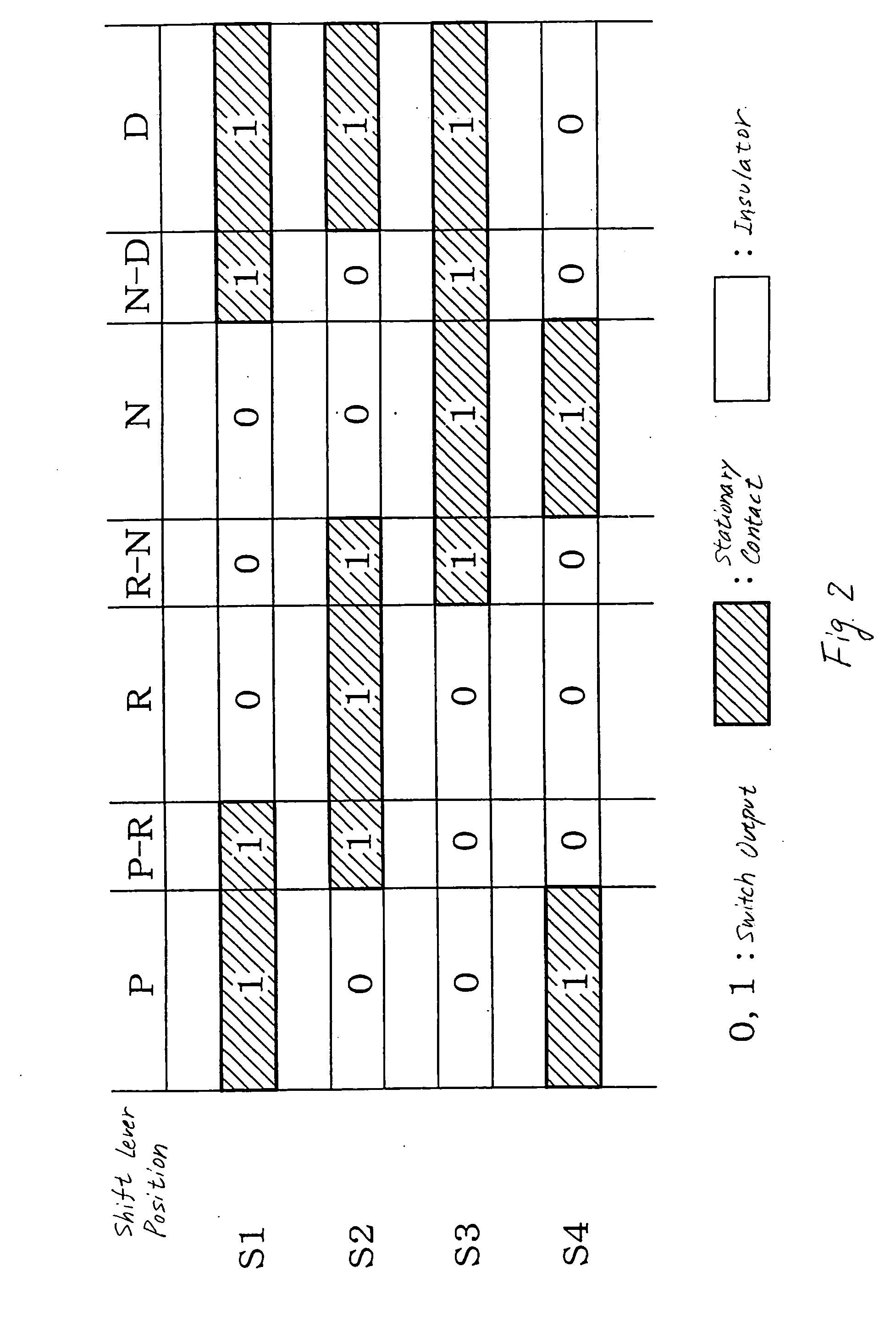
[0156] The automatic transmission 110 is designed to change the gear ranges in a shift pattern of P-R-N-D. The shift lever position sensor 12, like that in the first embodiment, is designed to monitor a total of seven shift lever positions: the P position, the R position, the N position, the D position, the P-R position, the R-N position, and the N-D position.

[0157] The seven shift lever positions, as described above, are each expressed by a three-bit code.

[0158] Generally, it is possible for the three-bit code to represent 23=eight (8) binary patterns. The number of positions of the gear shift lever 11 to be monitored by the shift lever position sensor 12 is, as described above, seven (7). The AT control system of this embodiment does not use one of the eight bit patterns in determining the position of the gear shift lever 11. Specifically, the AT control system is designed to use seven of the eight bit patterns for representing the positions of the gear shift lever 11 except one,...

third embodiment

[0228] the invention will be described below.

[0229]FIGS. 22 and 23 show modifications of the gear change initiation decision and the gear change completion / gear holding decision, as made in the programs of FIGS. 19 and 20.

[0230] While the AT-ECU 30 of the second embodiment works to observe a gear change action (i.e., initiation of a gear change or holding of a selected gear) of the automatic transmission 110 when the deemed D-position hydraulic transmission control is performed by monitoring a change in the input shaft speed Nt, the AT-ECU 30 of this embodiment is designed to achieve such an observation using a change in gear ratio GR of the automatic transmission 110. The gear ratio GR is mathematically determined in the AT-ECU 30 by a ratio of the input shaft speed Nt, as measured by the input shaft speed sensor 28, to the output shaft speed No, as measured by the output shaft speed sensor 29 (i.e., GR=Nt / No).

[0231] The AT-ECU 30 performs the programs illustrated in FIGS. 22 and...


PUM


Abstract

An automatic transmission control system equipped with a shift lever position sensor which includes a plurality of switches which output binary signals following a shifting motion of a gear shift lever. Patterns of combinations of the switch outputs are preselected so as to represent positions to which the gear shift lever is manually shiftable. The switches are broken down into two groups each of which produces a binary code carrying information about the position of the gear shift lever to monitor a failure in operation of the shift lever position sensor. The control system also works to perform a deemed D-position hydraulic transmission control to ensure the running of the vehicle even if the shift lever position sensor is failing.

Description

CROSS REFERENCE TO RELATED DOCUMENT [0001] The present application claims the benefits of Japanese Patent Application Nos. 2003-412320, 2003-412321, and 2004-24932 filed on Dec. 10, 2003, Dec. 10, 2003, and Jan. 30, 2004, the disclosures of which are incorporated herein by reference. BACKGROUND OF THE INVENTION [0002] 1. Technical Field of the Invention [0003] The present invention relates generally to an automatic transmission control system for automotive vehicles, and more particularly to such a system working to monitor a failure in operation of a shift lever position sensor and / or to ensure running of the vehicle if the shift lever position sensor is failing. [0004] 2. Background Art [0005] Japanese Patent First Publication No. 2003-294134 discloses a shift lever position sensor implemented by an inhibitor switch equipped with four contacts S1, S2, S3, and S4 which are turned on or off following the motion of a gear shift lever manually shifted by a vehicle driver. Patterns of ...

Claims


Application Information

Patent Timeline
IPC IPC(8): F16H59/00F16H59/10F16H61/02F16H61/12F16H61/18
CPCF16H59/105F16H61/12Y10T74/19251F16H2061/1284F16H2061/122
Inventor KOZAKI, TETSUJITAKAGI, AKIRAMURAKAWA, TAKAJI
Owner DENSO CORP
Why Eureka
Try Eureka