

Inks for use in membrane image transfer printing process
a technology of membrane image transfer and ink, which is applied in the field of inks, can solve problems such as defects in applied prin
- Summary
- Abstract
- Description
- Claims
- Application Information
AI Technical Summary
Benefits of technology
Problems solved by technology
Method used
Image

Examples
example 1
Preparation of Ink Formulation(s)
[0055] Six commercial screen printing and five commercial pad printing inks were identified for characterization. Each of these inks was selected due to their ability to adhere to plastic substrates. A total of 250 grams of each ink system was prepared by adding to the ink an appropriate amount of a solvent (retarder or thinner) according to the manufacturer's directions. Table 4 describes the composition of each thermal curable ink. One additional screen printing ink system (ink # SC-7) was prepared as a 4:1 mixture of two other screen printing inks, namely ink #s SC-1 and SC-4. These two inks were mixed together under low shear conditions to create the new formulation (ink # SC-7). Each of the screen printing (ink #s SC-1 to SC-7) and pad printing (ink #s PD-1 to PD-5) ink systems was used in the subsequently described examples for identifying the rheological properties preferred for membrane image transfer printing.
TABLE 4Ink ID (ResinInk Amoun...
example 2
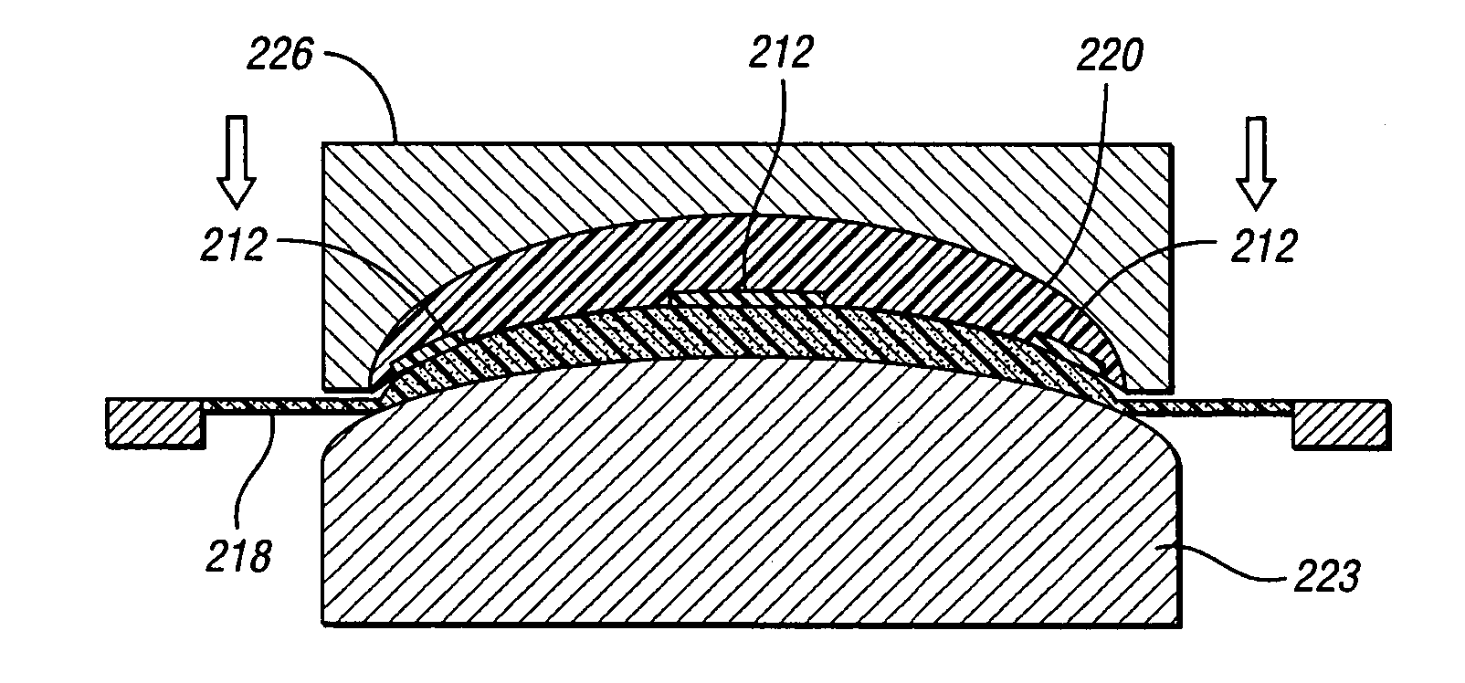
Compatibility with Membrane Image Transfer (MIT) Printing
[0056] The ink formulations prepared in Example 1 were subjected to Membrane Image Transfer (MIT) printing under identical conditions utilizing two different transfer time sequences. The MIT printing apparatus used to apply the print to a polycarbonate substrate is described in U.S. patent publication #2003-0116047. A 200 mesh screen with a 17 Newton tension was utilized to apply the print to a flexible silicone membrane. The atmospheric temperature was about 25° C. with a relative humidity varying between 46 to 61%. The time (TH) between the application of the print onto the membrane and the initiation of the transfer of the print from the membrane to the substrate was varied between two settings, either 15 seconds or 35 seconds. Although the transfer pressure was maintained in all runs at about 40 psi, the print transfer time (PTT) was also varied between two settings, namely, either 10 seconds or 25 seconds. Thus the overa...
example 3
Thixotrophy
[0064] The performance of all of the formulated screen printing inks (#s SC-1 to SC-7) and pad printing inks (#s PD-1 to PD-5) from Example 1 were characterized in a conventional rheological test called a thixotropic loop test at 25° C. This particular Theological test was performed on a Rheometrics RD-1i stress controlled rheometer at 25° C. The test cell geometery was a 40 mm cone & plate with a cone angle of 0.0394 radians and a gap between the cone and plate of 0.0787 mm. The ink was placed into the test cell and conditioned by being subjected to a shear rate of 300 sec−1 for 1 minute followed by 3 minutes at a zero shear rate (0 sec−1). The test was then initiated via ramping the applied stress up to a maximum of 10,000 dynes / cm2. A total of 50 measurements were taken over the 20 seconds to slowly ramp the applied stress in the first zone (up-curve). A similar sequence was then followed by ramping the applied stress (10,000 dynes / cm2) down to a natural resting state...
PUM
| Property | Measurement | Unit |
|---|---|---|
| Fraction | aaaaa | aaaaa |
| Force | aaaaa | aaaaa |
| Force | aaaaa | aaaaa |
Abstract
Description
Claims
Application Information