Method for formation of titanium nitride films

a titanium nitride and film technology, applied in the direction of turning apparatus, chemical vapor deposition coating, ion implantation coating, etc., can solve the problems of limiting the process of film deposition, the substrate size also limits the duration of film deposition, and the film is produced by these techniques. , to achieve the effect of relatively short film synthesis and not sacrificing the quality of the film

a titanium nitride and film technology, applied in the direction of turning apparatus, chemical vapor deposition coating, ion implantation coating, etc., can solve the problems of limiting the process of film deposition, the substrate size also limits the duration of film deposition, and the film is produced by these techniques. , to achieve the effect of relatively short film synthesis and not sacrificing the quality of the film

US20050126903A1Inactive Publication Date: 2005-06-16UNIV OF THE PHILLIPPINES DILLMAN

Image

  • Method for formation of titanium nitride films
  • Method for formation of titanium nitride films
  • Method for formation of titanium nitride films

Examples


Embodiment Construction

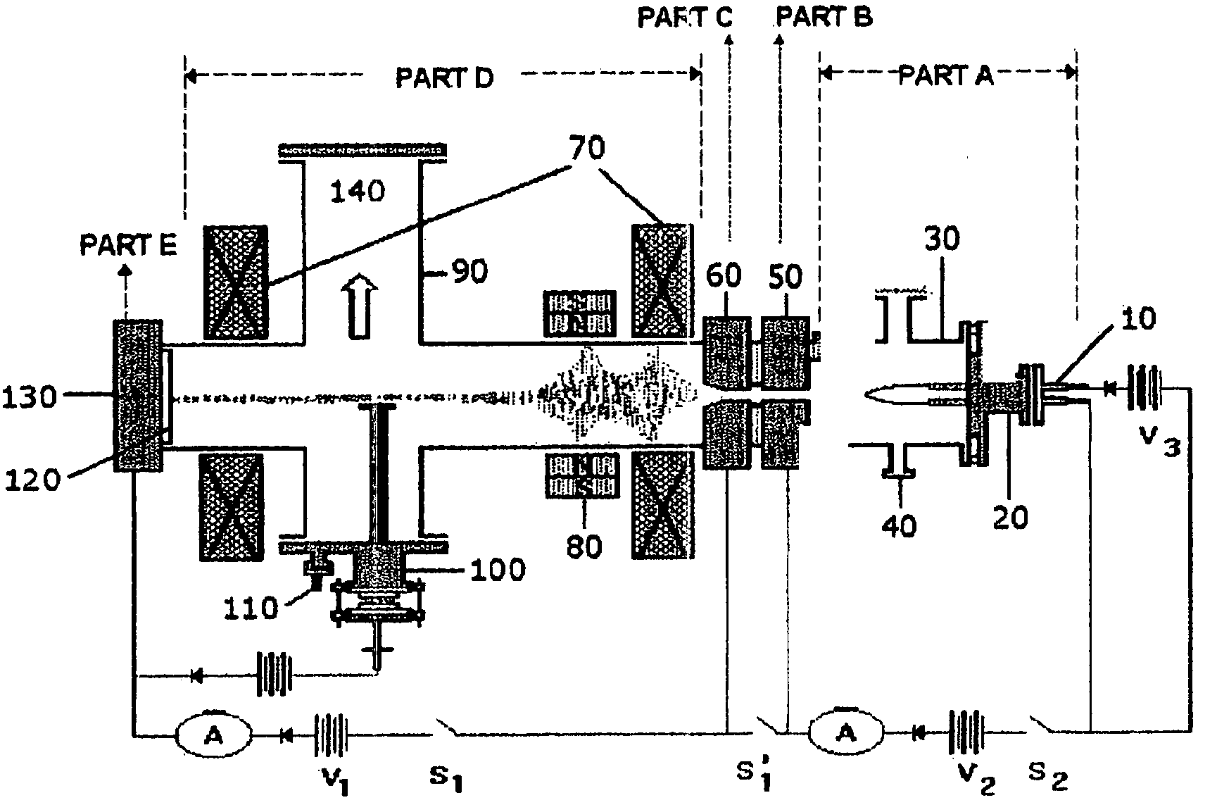
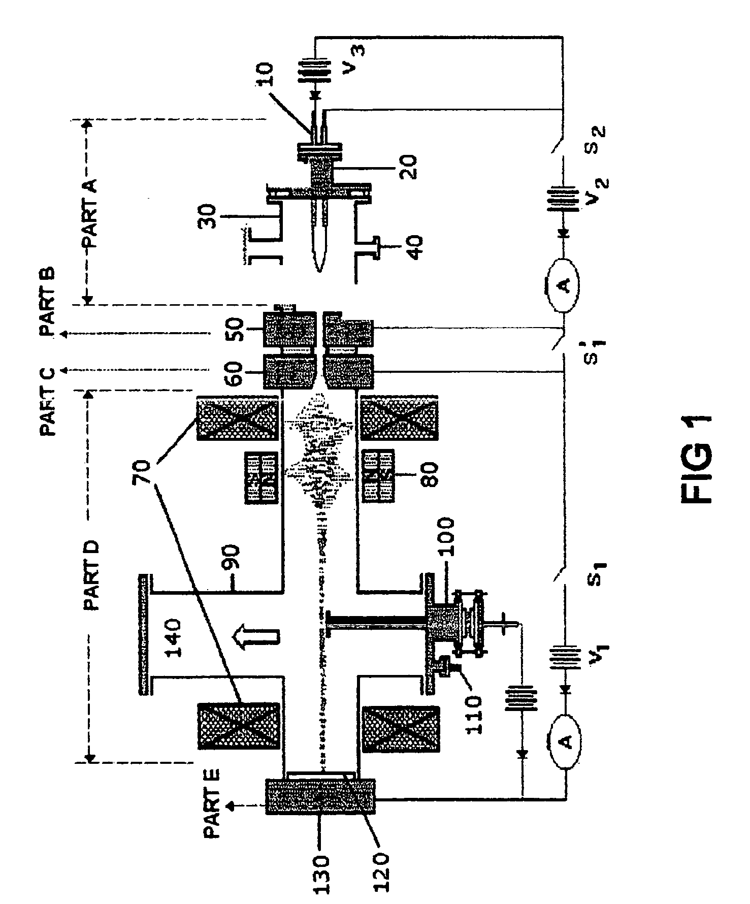
[0013] The teachings of the present invention can be readily understood with reference to the accompanying figures, in which details of the preferred manner of practicing the present art are described. Accordingly, persons of skill in the appropriate arts may modify the disclosures of the present invention but still obtain the favorable results described herein. Since the plasma source and its discharge characteristics are key to the deposition process, a description of the same is in order.

[0014] Referring to FIG. 1, the plasma source is composed of five main parts namely: the production chamber, shown as Part A in the diagram, the first and second plasma limiters, referred to as Parts B and C, respectively in the diagram, the main discharge vacuum chamber, referred to as Part D in the diagram, and the anode or end target, referred to as Part E in the diagram. Subsequent parts referring to FIG. 1 are numbered correspondingly as the description proceeds.

[0015] In this particular s...


PUM

PropertyMeasurementUnit
pressureaaaaaaaaaa
pressureaaaaaaaaaa
currentaaaaaaaaaa

Abstract

A procedure for the synthesis of titanium nitride (TiN) thin films on metal substrate by vapor deposition using a magnetized sheet plasma source is disclosed. TiN films on metal substrate exhibiting the stoichiometric TiN and Ti2N were synthesized in a mixed N2 / Ar plasma with initial gas filing ratio of preferably 1:3 under the following conditions: total initial gas filing pressure of at least about 40 mTorr, plasma current in the range of about 2A to 3A and plasma discharge potential in the range of about 125V to about 150V.

Description

FIELD OF THE INVENTION [0001] The invention relates to a method of film deposition. More particularly, the invention relates to a titanium nitride film chemical vapor deposition process on metal substrate using a magnetized sheet plasma source. BACKGROUND OF THE INVENTION [0002] Interest in new coatings and surface treatment methods has been on the upsurge during the last decade of the 1990s, especially for titanium nitride (TiN), gauging from the number of papers / patents published on this ceramic material. Titanium nitride films prepared on silicon are widely used as diffraction barrier layers in large-scale integrated circuits. A TiN film is also a remarkably hard and wear-resistant coating on tools since it decreases the rate of abrasive wear during the cutting process as well as the chemical interaction between the tool and the work piece because of its chemical inertness. TiN is a very stable compound that enhances the pitting resistance of many substrate materials in most envi...

Claims


Application Information

Patent Timeline
16 Jun 2005
Publication
US20050126903A1
IPC
B23B27/14; C23C14/06; C23C14/32; C23C14/35; H01L21/28; H01L21/285
CPC
C23C14/325; H01J2237/3142; H01J2237/08; C23C14/355
Inventors
RAMOS, HENRY J