Premixed air-fuel mixture supply device

a technology of premixed air and premixed mixture, which is applied in the direction of combustible gas purification/modification, lighting and heating apparatus, and separation processes, etc., can solve the problems of deteriorating combustion quality of premixed air-fuel mixture in the combustion chamber, and the inability to satisfactorily atomize and vaporize fuel, so as to prevent the deterioration of combustion in the combustor

Active Publication Date: 2005-06-16
KAWASAKI HEAVY IND LTD
View PDF26 Cites 3 Cited by
  • Summary
  • Abstract
  • Description
  • Claims
  • Application Information

AI Technical Summary

Benefits of technology

[0013] The present invention has been made to solve those problems in the prior art and it is therefore an object of the present invention to provide a premixed air-fuel mixture supply device for a gas turbine or an aircraft engine, capable of improving combustion in the combustor of the gas turbine or the aircraft engine.
[0029] The premixed air-fuel mixture supply device of the present invention has the secondary air passage formed around the prevaporizing, premixing chamber, and the atomization lip formed in the tail part of the inner wall of the secondary air passage. Therefore, the fuel spread in a liquid film over the outer wall of the prevaporizing, premixing chamber can be atomized at the edge of the atomization lip by air flowing along the outer and the inner surface of the atomization lip, so that the deterioration of combustion in the combustor can be prevented.

Problems solved by technology

The following problems arise when this previously proposed prevaporized, premixed air-fuel mixture lean-burn type combustor uses both the pilot fuel and the premixed air-fuel mixture while the combustor is in a low-load operation.
The fuel injected by the premixed air-fuel mixture supply device is unable to vaporize in the prevaporizing, premixing chamber because the temperature of air around the fuel is comparatively low, unvaporized fuel drops mixed in the swirling air are caused to adhere to a wall defining the prevaporizing, premixing chamber by centrifugal force and the fuel cannot be satisfactorily atomized and vaporized.
Consequently, the quality of combustion of the premixed air-fuel mixture in the combustion chamber is deteriorated.

Method used


Image

  • Premixed air-fuel mixture supply device
  • Premixed air-fuel mixture supply device
  • Premixed air-fuel mixture supply device

Examples


first embodiment

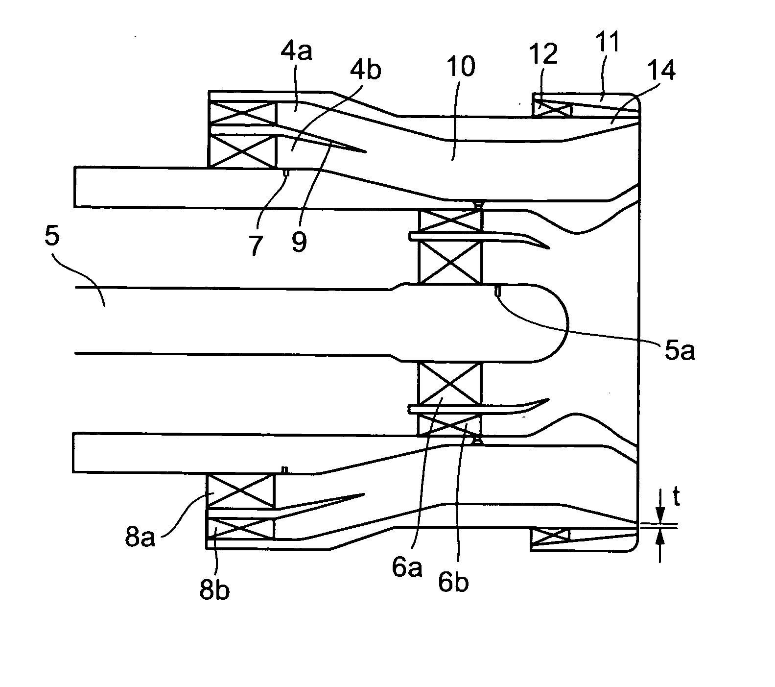
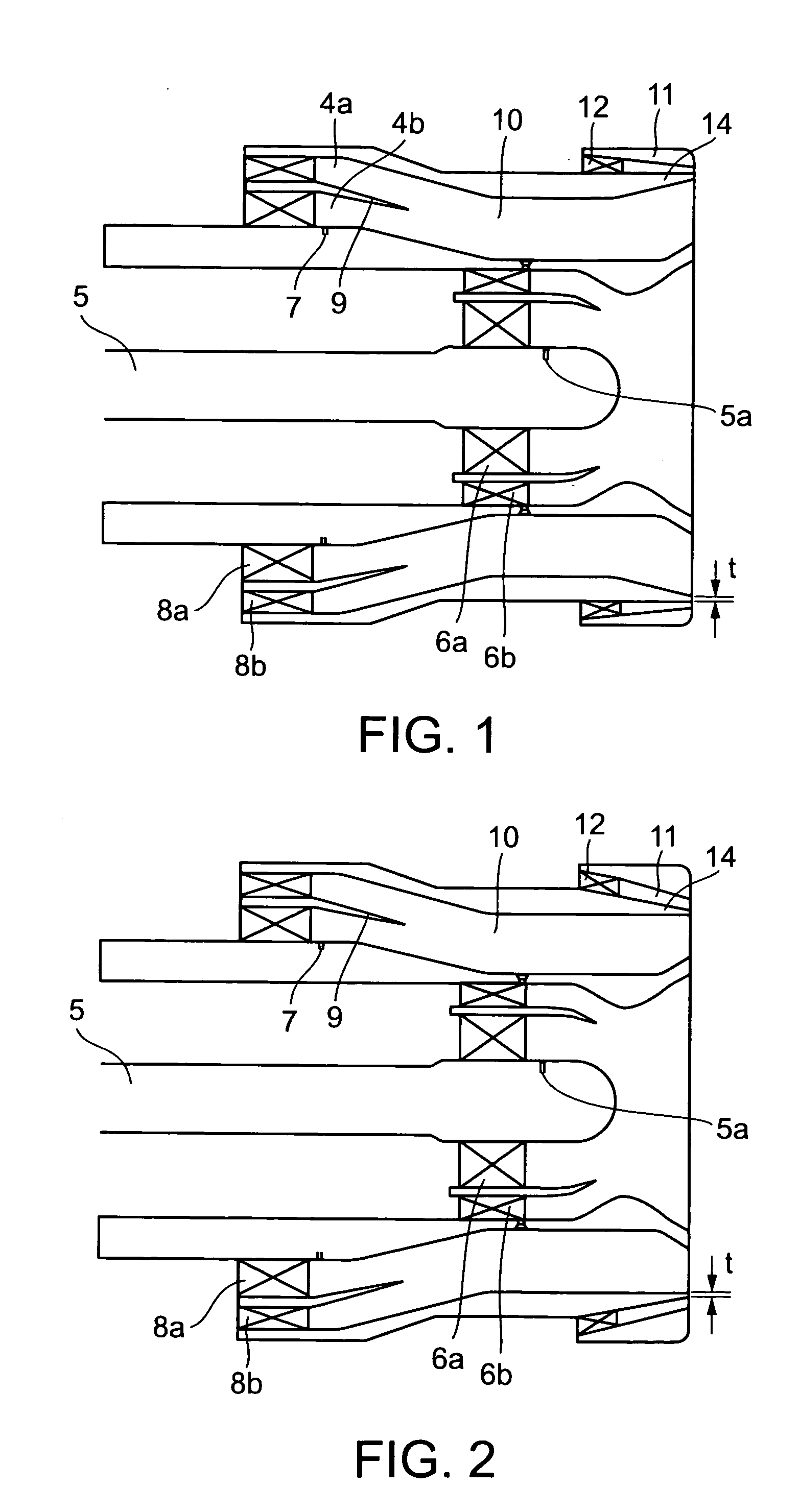
[0036] Referring to FIG. 1, the premixed air-fuel mixture supply device in the first embodiment, a pilot fuel injection unit is similar to the conventional fuel injection unit, and a main fuel injection unit is similar to that shown in FIG. 4. A secondary air passage 11 is formed around a prevaporizing, premixing chamber 10. A swirling device 12 for producing swirling air currents is disposed in the secondary air passage 11. The thickness of a tail part of an outer wall defining the prevaporizing, premixing chamber 10 is decreased toward a combustion chamber, not shown, to form a downstream atomization lip 14 having an inside diameter gradually increasing toward the combustion chamber.

second embodiment

[0037] In the premixed air-fuel supply device in the second embodiment shown in FIG. 2, a tail part of an outer wall defining a prevaporizing, premixing chamber 10 is decreased toward a combustion chamber, not shown, to form a downstream atomization lip 14 having an outside diameter gradually decreasing toward the combustor.

[0038] Description will be made of only the premixed air-fuel mixture supply device in the first embodiment will be described because the premixed air-fuel mixture supply devices in the first and the second embodiment are substantially the same in construction.

[0039] Main fuel is injected through main fuel injecting holes 7 into air currents flowing through an air passage 4b in directions substantially perpendicular to the flowing direction of the air currents. Such a mode of injecting the main fuel is not restrictive, and the main fuel does not necessarily need to be injected substantially perpendicularly to the flowing direction of the air currents. For exampl...


PUM

PropertyMeasurementUnit
thicknessaaaaaaaaaa
areaaaaaaaaaaa
total sectional areaaaaaaaaaaa

Abstract

A premixed air-fuel mixture supply device combined with a combustor liner included in a combustor comprises a prevaporizing, premixing unit having inner and outer walls defining a prevaporizing, premixing chamber, and a wall surrounding an end part of the outer wall so as to define a secondary combustion air passage together with the end part of the outer wall around the prevaporizing, premixing chamber. A tail part of the outer wall is shaped in an atomization lip. The extremity of the tail part of the atomization lip is formed in a sharp edge or is cut perpendicularly or substantially perpendicularly to the flowing direction of the combustion air.

Description

BACKGROUND OF THE INVENTION [0001] 1. Field of the Invention [0002] The present invention relates to a premixed air-fuel mixture supply device for supplying a premixed air-fuel mixture to a combustor for a gas turbine or an aircraft engine and, more particularly, to a premixed air-fuel mixture supply device for supplying a premixed air-fuel mixture to a combustor to make the combustor combust a premixed air-fuel mixture in a lean-burn mode, reduce NOx and prevent the deterioration of combustion while the combustor is in a low-load operation. [0003] 2. Description of the Related Art [0004] A conventional combustor for a gas turbine or an aircraft engine has a combustor casing, and a cylindrical or annular combustor liner disposed in the combustor casing to define a combustion chamber. A fuel nozzle is connected to a head part of the combustor liner. The combustor casing and the combustor liner define an air passage through which air supplied by an air compressor flows into the combus...

Claims


Application Information

Patent Timeline
Patent Type & Authority Applications(United States)
IPC IPC(8): F23R3/14F23R3/28F23R3/30
CPCF23D2900/11101Y10S261/55F23R3/30F23R3/286
Inventor ODA, TAKEONINOMIYA, HIROYUKIKOBAYASHI, MASAYOSHI
Owner KAWASAKI HEAVY IND LTD
Why Eureka
Try Eureka