Indexing rotatable chuck for a probe station

a rotary chuck and probe station technology, applied in the direction of individual semiconductor device testing, semiconductor/solid-state device testing/measurement, instruments, etc., can solve the problems of achieve the effect of promoting rigidity and consistent planarity, reducing shaft length, height and mass of the rotary chuck

Inactive Publication Date: 2005-06-16
CASCADE MICROTECH
View PDF2 Cites 22 Cited by
  • Summary
  • Abstract
  • Description
  • Claims
  • Application Information

AI Technical Summary

Benefits of technology

[0011] The present invention overcomes the aforementioned drawbacks of the prior art by providing a chuck for a probe station comprising a base attached to the probe station; a shaft mounted for rotation in the base; and a device mounting member affixed to the shaft for rotation therewith and having a planar orientation relative to said base substantially independent of the orientation of the shaft to the device mounting member. A large diameter resilient seal between the base and the device mounting member supports the device mounting member independent of the alignment of the shaft promoting rigidity and consistent planarity. Further, this method of support reduces the length of the shaft and, consequently, the height and mass of the rotary chuck. In addition, the rotary chuck can include a releasable rotation stop to permit indexed rotation of the device mounting member to a new test position. In another embodiment, a chuck for a probe station comprises a base attached to the probe station and a device mounting member constrained by the base for rotation relative thereto.

Problems solved by technology

Further, this method of support reduces the length of the shaft and, consequently, the height and mass of the rotary chuck.

Method used


Image

  • Indexing rotatable chuck for a probe station
  • Indexing rotatable chuck for a probe station
  • Indexing rotatable chuck for a probe station

Examples


Embodiment Construction

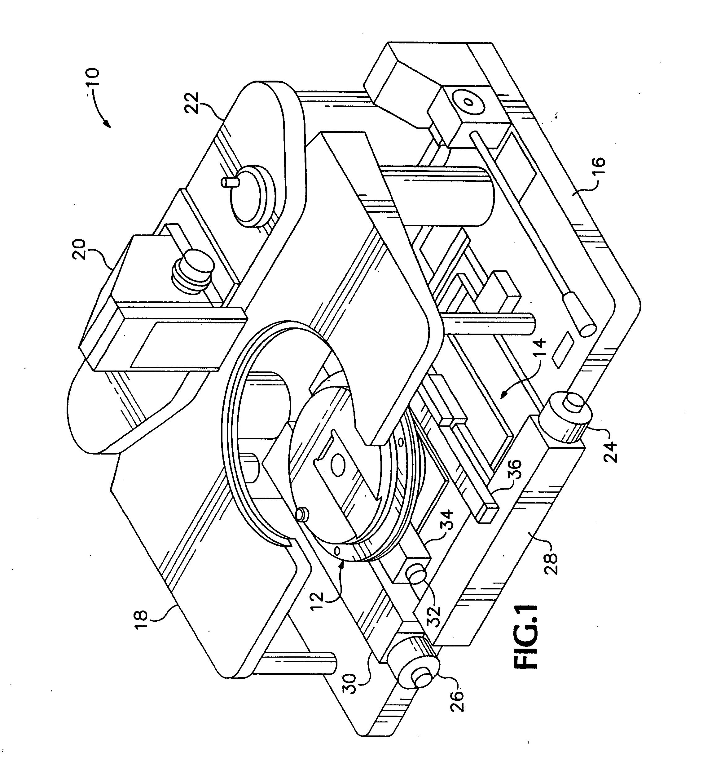
[0017] Referring to FIG. 1, in a probe station 10 a device under test (DUT) is mounted on a chuck 12 which is supported on a movable stage 14 mounted on a station base 16. Probes (not illustrated) are supported over the chuck by a platen 18. The probes are provided with controls for positioning along horizontal (x and y) axes and the platen 18 may be adjusted in the vertical (z) direction to bring the probes into contact with test points on the integrated circuit of the DUT. To facilitate location and positioning of the probes, the probe station 10 includes a microscope (not illustrated) mounted on a microscope mounting 20 attached to an optics bridge 22. The probe station 10 may include an environmental housing (not illustrated) to protect the DUT and probes from dust and other environmental hazards.

[0018] To facilitate relative positioning of the DUT and probes, the stage 14 provides for translatory and limited rotational (theta) movement of the chuck 12. In the probe station 10 ...


PUM


Abstract

A rotary chuck with indexed rotation promotes rapid rotation of a device under test and increases the productivity of a probe station on which the device is being tested. A device mounting member of a rotatable chuck is supported for rotation on a first surface of a base until a vacuum is applied drawing the device mounting member into contact with a second surface of the base and constraining the device mounting member against rotation.

Description

CROSS-REFERENCE TO RELATED APPLICATIONS [0001] This is a continuation of application Ser. No. 10 / 856,279, filed May 28, 2004, which is a continuation of application Ser. No. 10 / 179,796, filed Jun. 24, 2002, now U.S. Pat. No. 6,771,090, which is a continuation of application Ser. No. 09 / 564,591, filed May 3, 2000, now U.S. Pat. No. 6,483,336.BACKGROUND OF THE INVENTION [0002] The present invention relates to a chuck for a probe station and, more particularly, to an indexing, rotatable chuck for securing a device under test in a probe station. [0003] Integrated circuits (ICs) comprise micro-circuits chemically etched on semiconductor material or wafers. It is customary to manufacture several ICs on a single wafer and then separate the individual circuits after performance and functional testing in a wafer probe station. Probe stations are also used for testing the performance and function of an IC after the IC has been incorporated into a composite device. [0004] Generally, a probe st...

Claims


Application Information

Patent Timeline
Patent Type & Authority Applications(United States)
IPC IPC(8): G01R31/26G01R1/04G01R31/28H01L21/00H01L21/66H01L21/68H01L21/683
CPCG01R1/0408H01L21/6835H01L21/67271G01R31/2831
Inventor HARRIS, DANIEL L.MCCANN, PETER R.
Owner CASCADE MICROTECH
Why Eureka
Try Eureka