Ultra fast, low noise voltage feedback operational amplifier with dynamic biasing

a dynamic biasing and low noise technology, applied in differential amplifiers, amplifier details, amplifiers with semiconductor devices/discharge tubes, etc., can solve the problems of limiting the resolution of output signals and its noise performance is not as good when compared to single differential pair inputs, and achieves low distortion, high slew rate, and full power bandwidth

Active Publication Date: 2005-06-16
TEXAS INSTR INC
View PDF5 Cites 19 Cited by
  • Summary
  • Abstract
  • Description
  • Claims
  • Application Information

AI Technical Summary

Benefits of technology

[0007] The present invention achieves technical advantages as an operational amplifier having both a high slew rate and a full power bandwidth with low distortion by providing resistors in place of active loads of a differential pair of transistors in a folded cascode input stage. By utilizing passive resistors instead of active loads, no saturation occurs during high slew rate signals. The present invention achieves technical advantages of higher slew rate and lower noise without sacrificing power consumption. While more transistors are required for the operational amplifier of the present invention when compared to other architectures, there is no significant sacrifice in power consumption. This is due to the fact that dynamic bias circuit feeding the input stage does not have to be large to lower the noise at the input stage. The noise contribution of the dynamic bias stage is completely negligible with respect to the rest of the amplifier because it does not have gain from the input to the output of the operational amplifier.

Problems solved by technology

Unfortunately, current solutions increase full power bandwidth by sacrificing noise performance in the amplifier thus limiting the resolution of the output signal.
The input stage 12 is fast, but its noise performance is not as good when compared to single differential pair inputs.
This limitation calls for a new dynamically biased circuit that does not suffer from saturation during high slew signals and yet maintains low noise operation without trading off power.

Method used


Image

  • Ultra fast, low noise voltage feedback operational amplifier with dynamic biasing
  • Ultra fast, low noise voltage feedback operational amplifier with dynamic biasing
  • Ultra fast, low noise voltage feedback operational amplifier with dynamic biasing

Examples


Embodiment Construction

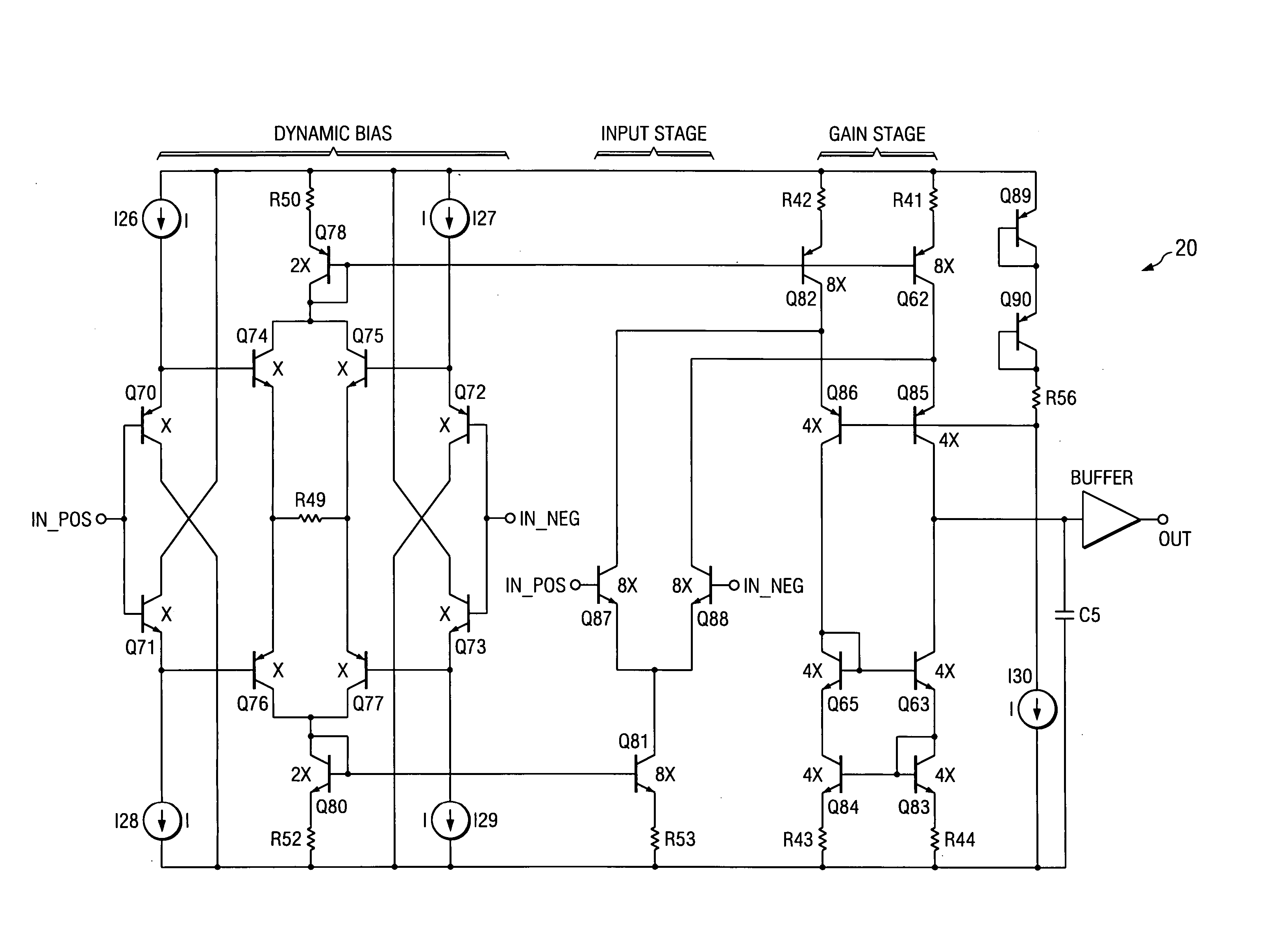
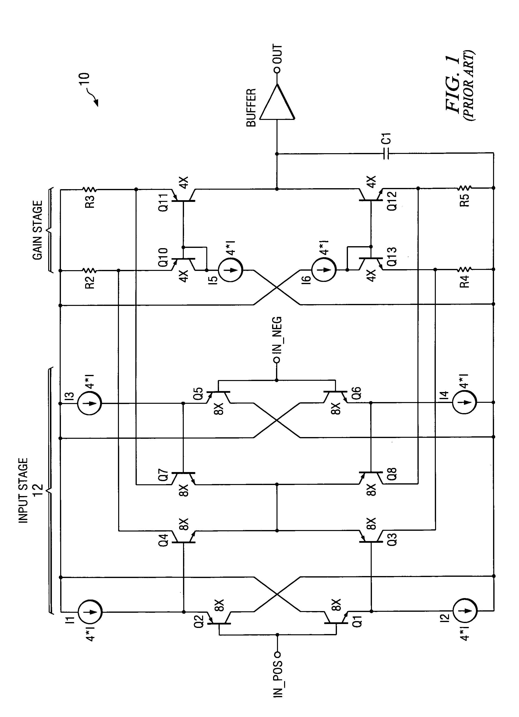
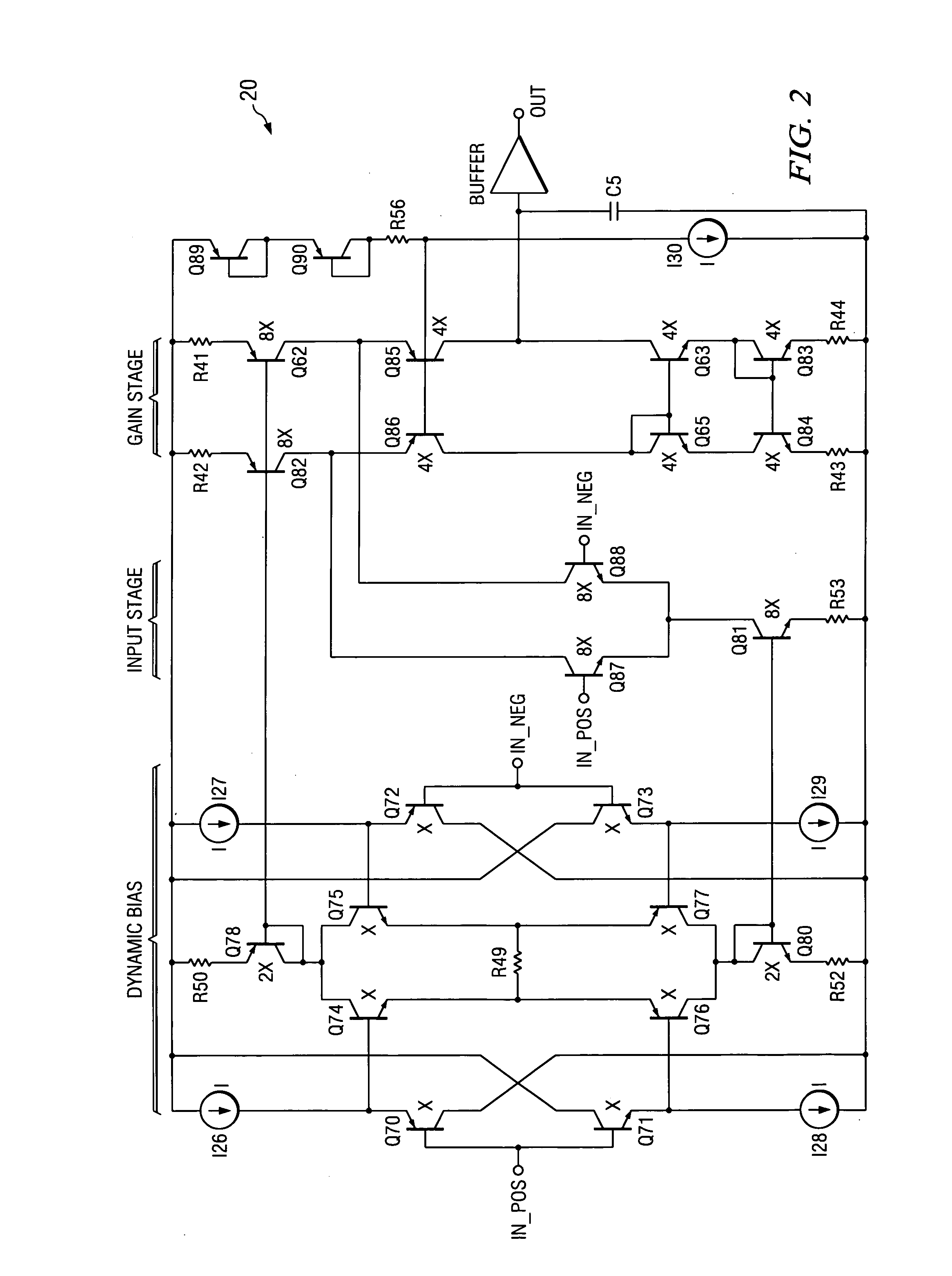
[0013] An operational amplifier that does not suffer from saturation during high slew rate signals and maintains low noise operation without trading off power is shown at 30 in FIG. 3. This circuit 30 uses resistors instead of active loads. Advantageously, no saturation occurs during fast signals, and circuit 30 accomplishes higher slew rate and lower noise performance without sacrificing power consumption. More transistors are required in amplifier 30 when compared to the circuits 10 and 20, but no significant sacrifice is observed in its power consumption. This is due to the fact that the dynamic bias circuit 32 does not have to be large to lower the noise at the input stage 34. The noise contribution of the dynamic bias stage 32 is completely negligible to the rest of the amplifier 30 including gain stage 36 because it does not have gain from the differential input 38 to the output 39 of the amplifier.

[0014] The circuit 30 in FIG. 3 accomplishes very low noise because the input ...


PUM


Abstract

The present invention achieves technical advantages as an operational amplifier (30) having both a high slew rate and a full power bandwidth with low distortion by providing resistors (R6, R7, R9, R10) in place of active loads coupled to a differential pair (Q22, Q25, and Q23, Q24) of transistors in a folded cascode input stage (34). By utilizing passive resistors instead of active loads, no saturation occurs during high slew rate signals. The present invention achieves technical advantages of higher slew rate and lower noise without sacrificing power consumption.

Description

RELATED PATENT APPLICATIONS [0001] Cross reference is made to co-pending commonly assigned U.S. patent application Ser. No. 09 / 999,475 filed Dec. 3, 2001 and entitled “Bipolar Class AB Folded Cascode Operational Amplifier for High-Speed Applications” the teachings of which are incorporated herein by reference.FIELD OF THE INVENTION [0002] The present invention is related to operational amplifiers, and more particularly to high slew rate operational amplifiers with extremely low distortion. BACKGROUND OF THE INVENTION [0003] High speed operational amplifiers (op amps) are required to have high slew rates so that the full power bandwidth is higher and as a consequence lower distortion is achieved at higher frequencies and / or higher signal amplitudes. Unfortunately, current solutions increase full power bandwidth by sacrificing noise performance in the amplifier thus limiting the resolution of the output signal. [0004] An example of such a solution is the widely known class AB input st...

Claims


Application Information

Patent Timeline
Patent Type & Authority Applications(United States)
IPC IPC(8): H03F1/32H03F3/45
CPCH03F1/3211H03F3/45085H03F3/45094H03F2203/45684H03F2203/45454H03F2203/45626H03F2203/45248
Inventor PARKHURST, CHARLES
Owner TEXAS INSTR INC
Why Eureka
Try Eureka