Determination of correlation in the frequency domain

a frequency domain and correlation technology, applied in the field of correlation in the frequency domain, can solve the problems of significant computational burden and processing delays, and achieve the effects of optimizing data flow, optimizing memory space, and optimizing correlation

Inactive Publication Date: 2005-06-16
NOKIA CORP
View PDF6 Cites 22 Cited by
  • Summary
  • Abstract
  • Description
  • Claims
  • Application Information

AI Technical Summary

Benefits of technology

[0019] It is an advantage of the invention that it allows to optimize a correlation employed for example in the acquisition of a code modulated signal.
[0020] It is in particular an advantage of the invention that the memory space is used optimally by employing a single memory for various processing steps. Thereby, the size of the total required memory space can be reduced to one half.
[0021] In an embodiment of the invention, the same memory space is shared in addition for storing the samples of the code modulated signal before it is transformed into the frequency domain.
[0022] In a further embodiment of the invention using DIF FFT and DIF IFFT, a structure is employed, in which the data reorderings specific to DIF FFT and DIF IFFT algorithms are not needed for determining the correlation. This is achieved by an equivalent reordering of the frequency domain replica samples which are used in the correlation computations. These frequency domain replica samples can either be given by the conjugate of the replica samples transformed into the frequency domain or by the time to frequency transform of inverted replica samples. Moving the reordering in such a manner enables either to avoid reordering operations in a matched filter unit or it enables the continuous computation of butterfly operations without the need to communicate with a host processor between the DIF FFT and the DIF IFFT stages.
[0023] In a further embodiment o

Problems solved by technology

In case there is a large number of code phases to check, the computational burden is significant, especially for software based receivers.
Such a reordering has the d

Method used


Image

  • Determination of correlation in the frequency domain
  • Determination of correlation in the frequency domain
  • Determination of correlation in the frequency domain

Examples


Embodiment Construction

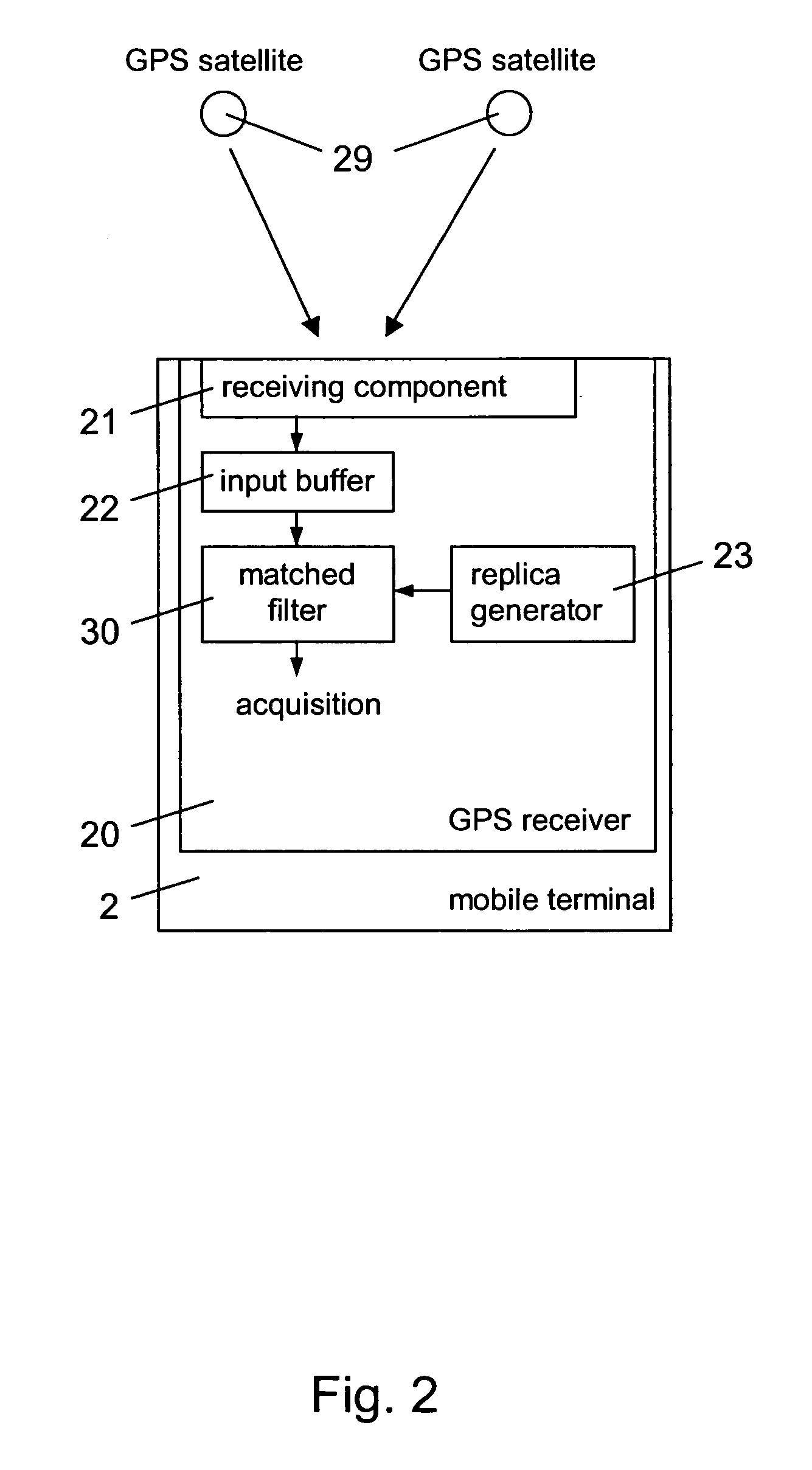
[0036]FIG. 2 presents by way of example a GPS receiver 20 in which the invention can be implemented for supporting the acquisition of satellite signals. The GPS receiver 20 may be part of a mobile terminal 2 or an autonomous GPS receiver.

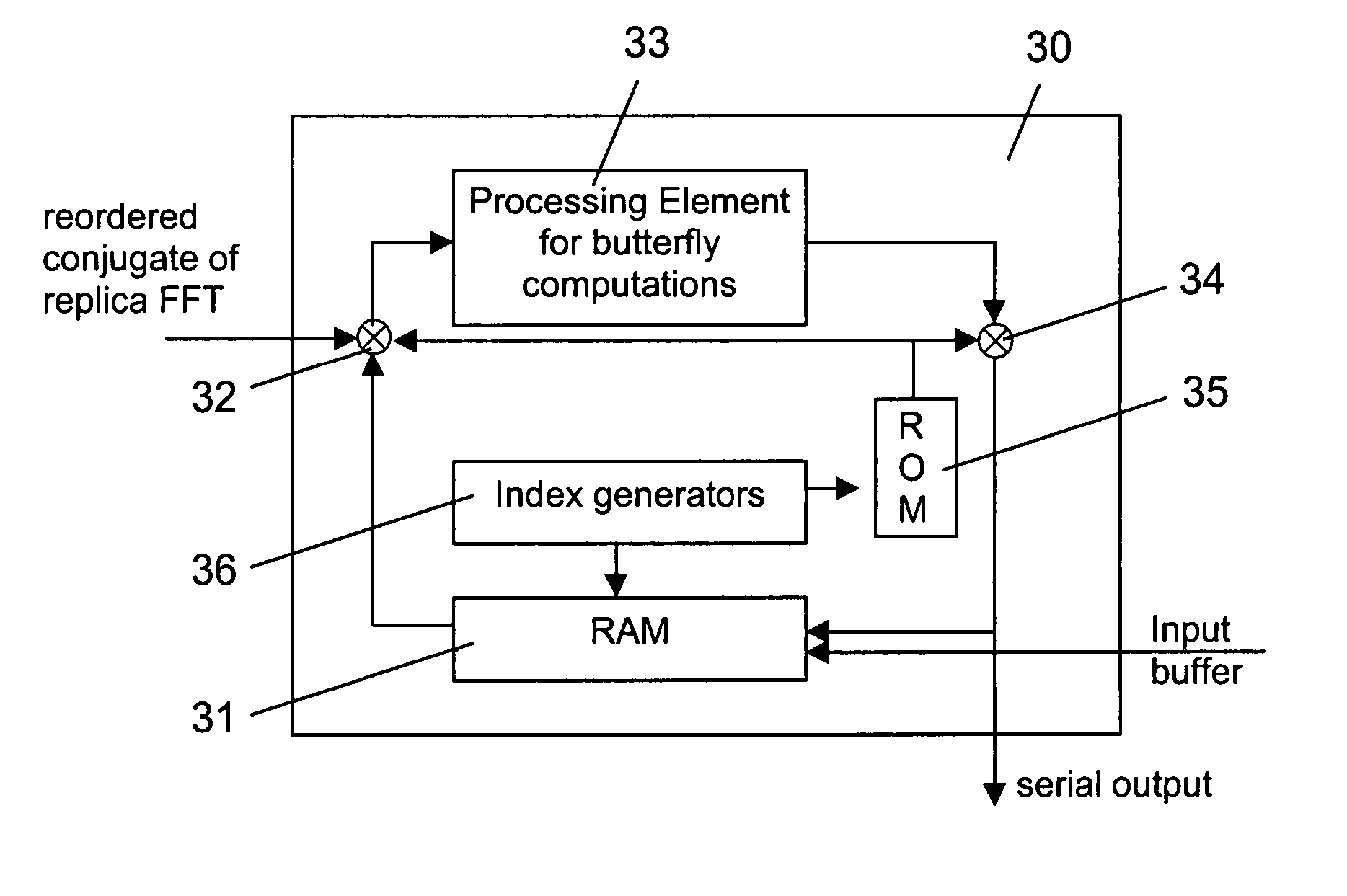
[0037] The GPS receiver 20 includes a receiving component 21 for receiving a code modulated signals transmitted by a GPS satellite 29 and an input buffer 22 for storing samples originating from a received satellite signal. The GPS receiver 20 further includes an FFT replica generator 23 for generating replica samples and a matched filter 40 for performing a correlation between samples from the input buffer 22 and replica samples provided by the FFT replica generator 23. The resulting correlation values are output by the matched filter 30 for enabling the final acquisition of the received satellite signal in a well known manner.

[0038] Further components of the GPS receiver 20, which are not shown, may correspond to any components of known GPS recei...


PUM


Abstract

The invention relates to a device for determining in the frequency domain the correlation between a code modulated signal and a replica code sequence in parallel for various relative shifts between the code modulated signal and the replica code sequence. The device comprises a common memory arranged for storing in sequence different intermediate results in determining the correlation. The intermediate results including at least samples resulting at various stages of a time to frequency transform used for transforming samples of the code modulated signal into the frequency domain and samples resulting at various stages of a frequency to time transform used for transforming obtained correlation results into the time domain. The invention relates equally to a corresponding system, to a corresponding method and to a corresponding software program product.

Description

FIELD OF THE INVENTION [0001] The invention relates to a device, a system, a method and a software program product for determining in the frequency domain the correlation between a code modulated signal and a replica code sequence in parallel for various relative shifts between the code modulated signal and the replica code sequence. BACKGROUND OF THE INVENTION [0002] A correlation between a code modulated signal and a replica code sequence has to be determined for example for the acquisition of code modulated signals at a CDMA (Code Division Multiple Access) spread spectrum receiver. [0003] For a spread spectrum communication in its basic form, a data sequence is used by a transmitting unit to modulate a sinusoidal carrier, and then the bandwidth of the resulting signal is spread to a much larger value. For spreading the bandwidth, the single-frequency carrier can be multiplied for example by a high-rate binary pseudo-random noise (PRN) code sequence comprising values of −1 and 1, ...

Claims


Application Information

Patent Timeline
IPC IPC(8): G06F17/15H04B1/707
CPCG01S19/29H04B1/7093G06F17/156G01S19/30
Inventor AKOPIAN, DAVID
Owner NOKIA CORP
Why Eureka
Try Eureka