
Signal delay time measurement device and computer program therefor

a signal delay time and measurement device technology, applied in the field of signal delay time measurement devices, can solve problems such as the failure of delay time calculating units, and achieve the effect of accurate measurement of signal delay tim

Inactive Publication Date: 2005-06-16
ONKYO KK D B A ONKYO CORP
View PDF7 Cites 9 Cited by
  • Summary
  • Abstract
  • Description
  • Claims
  • Application Information

AI Technical Summary

Benefits of technology

[0010] The present invention has been achieved in order to solve the above problems. It is an object of this invention to provide a signal delay time measurement device capable of excluding an effect of a background noise and performing an accurate measurement of a signal delay time.
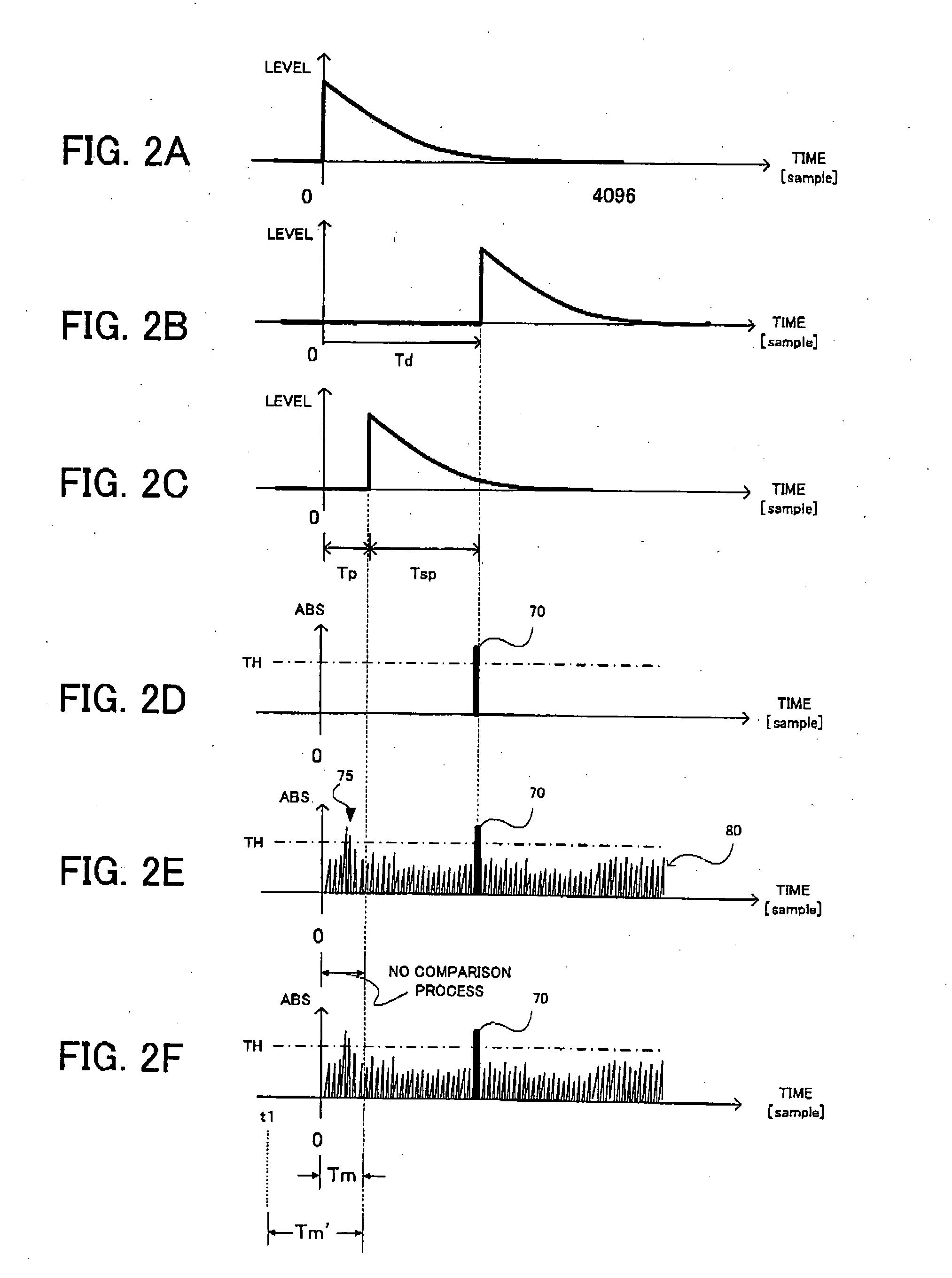
[0014] The above signal delay time measurement device outputs, to the sound space, the measurement signal sound corresponding to the measurement signal such as the pulse signal, and obtains the response signal indicating the response. By comparing the response signal with the predetermined threshold, the signal delay time measurement device measures the signal delay time in the above-mentioned sound space. The threshold is determined based on the background noise level in the sound space. The signal delay time in the above sound space includes the delay time other than the delay time caused by the transmission of the signal sound to the sound space, and the response signal cannot theoretically reach the signal delay amount calculating unit during the period. Namely, during the period, the background noise level in the sound space immediately before the actual signal delay time calculating process can be obtained. Therefore, the threshold determining unit sets the background noise measurement period to include the no-response period in which the response signal has not reached the delay time calculating unit yet, and the threshold is determined based on the measurement result of the background noise in the period. Thereby, since the threshold is determined based on the background noise obtained immediately before the actual signal delay time, it becomes possible to more accurately calculate the signal delay time.
[0016] In another manner, the signal delay time measurement device may further include a storage unit which stores the in-device delay time as a fixed value, and the no-response period may be set to a period of the in-device delay time from an output of the measurement signal. By storing the in-device delay time as the fixed value, it becomes possible to rapidly perform the measurement of the signal delay time.
[0017] In still another manner, the background noise measurement period may include a predetermined period before the measurement signal output unit outputs the measurement signal. Like this, by extending the background noise measurement period, it becomes possible to measure the variation of the background noise in a short time as much as possible to determine an effective threshold.
[0023] By the above-mentioned signal delay time measurement method, the signal delay time can accurately be calculated with eliminating the effect of the background noise during the no-response period.

Problems solved by technology

Therefore, the delay time calculating unit does not perform the comparison in the no-response period in which the response signal has not reached the delay time calculating unit yet.

Method used


Image

  • Signal delay time measurement device and computer program therefor
  • Signal delay time measurement device and computer program therefor
  • Signal delay time measurement device and computer program therefor

Examples


Embodiment Construction

[0037] The preferred embodiments of the present invention will now be described below with reference to the attached drawings.

[Basic Principle]

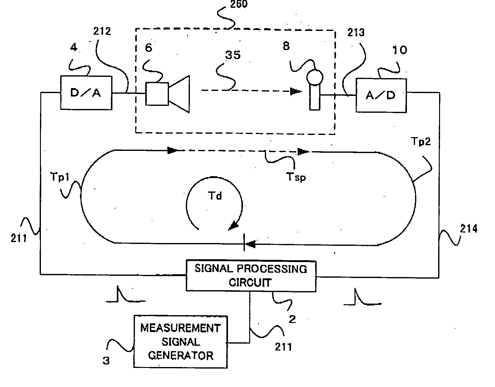
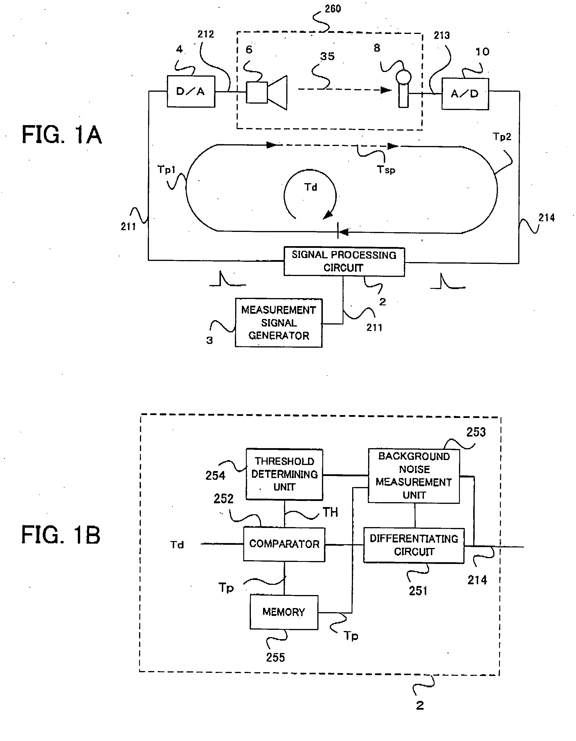
[0038] First, the description will be given of a basic principle of a signal delay time measurement according to the present invention. FIG. 1A schematically shows the basic configuration for the signal delay time measurement. As shown in FIG. 1A, the signal delay time measurement device includes a signal processing circuit 2, a measurement signal generator 3, a D / A converter 4, a speaker 6, a microphone 8 and an A / D converter 10. The speaker 6 and the microphone 8 are disposed in a sound space 260. It is noted that the sound space 260 may be a listening room, a home theater and the like, for example.

[0039] The measurement signal generator 3 generates the pulse signal (hereafter, referred to as “measurement pulse signal”) as a measurement signal 211, and supplies it to the signal processing circuit 2. The measurement pulse signal can be st...


PUM


Abstract

A signal delay time measurement device outputs, to a sound space, a measurement signal sound corresponding to a measurement signal such as a pulse signal, and obtains a response signal indicating a response thereof. By comparing the response signal with a predetermined threshold, the signal delay time measurement device measures a signal delay time in the sound space. The signal delay time in the above-mentioned sound space includes a delay time other than the delay time caused by a transmission of a signal sound to the sound space, and the response signal cannot theoretically reach the signal delay amount calculating unit during the delay time. Therefore, the delay time calculating unit does not perform the comparison in a no-response period in which the response signal has not reached the delay time calculating unit yet. Thereby, it can be prevented that the signal delay time is erroneously calculated by an effect of a background noise during the no-response period.

Description

BACKGROUND OF THE INVENTION [0001] 1. Field of the Invention [0002] The present invention relates to a signal delay time measurement device which measures a signal delay time in a sound space in an audio system including a plurality of speakers. [0003] 2. Description of Related Art [0004] For an audio system having a plurality of speakers to provide a high quality sound space, it is required to automatically create an appropriate sound space with much presence. In other words, it is required for the audio system to automatically correct sound field characteristics because it is quite difficult for a listener to appropriately adjust the phase characteristic, the frequency characteristic, the sound pressure level and the like of sound reproduced by a plurality of speakers by manually manipulating the audio system by himself to obtain appropriate sound space. [0005] So far, as this kind of automatic sound field correcting system, there is known a system disclosed in Japanese Patent App...

Claims


Application Information

Patent Timeline
Patent Type & Authority Applications(United States)
IPC IPC(8): H04R3/00H04R29/00G04F10/04H04S3/00H04S7/00
CPCH04S3/00H04S7/307H04S7/302H04S7/301
Inventor YOSHINO, HAJIME
Owner ONKYO KK D B A ONKYO CORP
Learn More