
Device for producing granules

a technology of granules and granules, which is applied in the direction of granulation on conveyor belts, applications, manufacturing tools, etc., can solve the problems of high belt wear, relatively expensive heating equipment, and high cost of belts of this type in their production, and achieves excellent heating retention capability, simple construction, and resistance to wear.

Inactive Publication Date: 2005-06-16
SANTRADE LTD
View PDF11 Cites 3 Cited by
  • Summary
  • Abstract
  • Description
  • Claims
  • Application Information

AI Technical Summary

Benefits of technology

[0005] Based on the premise that, for example, steel belts provided on a belt press have the necessary thickness for a drop-forming process and have excellent heating retention capability, it is proposed in the achievement of the object for a device of the aforementioned type that a steel belt used as a perforated belt has the sufficient thickness for the drop-forming process whereby said steel belt is guided around guide drums having sufficiently large diameters to prevent forming of cracks at the orifices, and whereby a heating element is arranged for the steel belt at least at a distance upstream from the drop-forming point. This measure requires, nevertheless, that guide drums in the range of approximately 1,000 mm have to be used in the employment of steel belts having a thickness between 1 mm and 4 mm, as they are also used in belt presses, whereby the heating capacity of such a steel belt is suitable in an extremely advantageous manner to be provided in a device of the aforementioned type. It has been shown that the drop-forming process can be surprisingly performed with different viscous substances at specific temperatures whereby heating of the steel belt can be respectively adjusted to the type of application. The employed smooth steel belts are of simple construction, very resistant to wear, and they can be easily cleaned as well.
[0006] In development of the invention, it is possible to arrange in a relatively simple manner the heating unit in the interior, at least in the guide drum that is disposed in front of the drop-forming process in the direction of movement of the lower flight of the steel belt. The interior of this large guide drum has easily enough space for all conceivable kinds of heating units with which the guide drum itself and also the perforated steel belt can be heated.
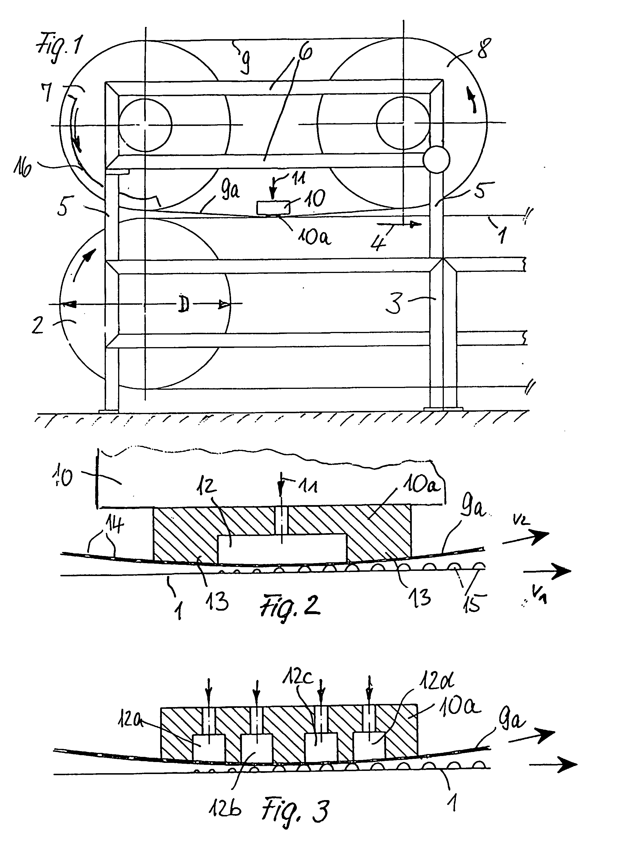
[0008] The discharge opening can also be in the form of a plurality of groove-like recesses running parallel to one another and extending transversely to the movement direction of the steel belt whereby all recesses lead to the surface of the container that rests against the steel belt. It has been shown that such a design is more favorable for the drop-forming process of some particular substances. In both cases-which also includes the use of a relatively wide groove-like recess in the direction of the belt movement—the relatively thick steel belt provided according to the invention offers the advantage that it does not force itself into the groove-like recess even though it is pressed firmly against the surface of the container facing outwardly.

Problems solved by technology

However, the use of plastic synthetic belts leads to relatively high wear of the belts.
However, since such a metal belt does not have the sufficient thickness to offer the necessary portion volume in the pickup of the substance to be dripped during the drop producing process, there are arranged outwardly projecting nozzles on the steel belt on all perforated openings at the side facing away from the container in order not to negatively influence the guidance of the belt and still serve to pick up the necessary portion volume.
Belts of this type are relatively costly in their production.
They have also the disadvantage, just like the traditionally used synthetic plastic belt, that relatively costly heating equipment has to be provided in the area of the drop-forming point to ensure necessary heating of the substances to be dripped and to avoid, at least at this point, premature solidifying of the material exiting the orifices.

Method used


Image

  • Device for producing granules
  • Device for producing granules

Examples


Embodiment Construction

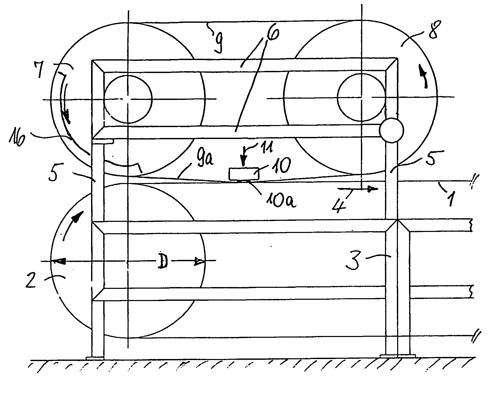
[0014]FIG. 1 shows that an endless revolving steel transport belt 1, which is designed as a cooling belt in a not further described manner, is held in a machine stand 3 with the aid of two guide rollers, of which only the guide roller 2 is shown. The cooling steel belt revolves in the direction of arrow 4. The depicted guide roller 2 has a diameter D of approximately 1,000 mm.

[0015] Two additional guide rollers 7 and 8 of approximately the same diameter as the one of the guide roller 2 are proposed to be in the machine stand 3, which is provided with a support frame 6 on vertical support pieces 5 extending upwardly. Said guide rollers 7 and 8 serve as guide and drive for an additional endless steel belt 9 that is perforated nearly across its entire width—which is only indicated in FIG. 2 and FIG. 3.

[0016] A lower flight 9a of the perforated steel belt 9 passes by the container 10, which is supplied with a flowable viscous substance in the direction of arrow 11 in a known manner, w...


PUM

PropertyMeasurementUnit
thicknessaaaaaaaaaa
thicknessaaaaaaaaaa
thicknessaaaaaaaaaa

Abstract

A belt drop shaper forms a viscous substance into the shape of drops. The drop shaper includes a container for the substance and a perforated steel belt pressing against a bottom surface of the container. The bottom surface includes at least one discharge opening that is periodically opened by perforations in the belt to enable drops of the substance to fall on a transport conveyor. A heater unit is provided, e.g., in a support drum around which the steel belt travels, to heat the steel belt at a location upstream of the discharge opening.

Description

BACKGROUND OF THE INVENTION [0001] The invention relates to a device for the production of granulates made of flowable, viscous substances comprising a container supplied with the substances having at least one discharge opening that is periodically opened and closed by a passing perforated belt so that the substances fall from the orifices in the form of drops onto a conveyor belt traveling below, particularly a belt designed as a cooling belt on which said substances solidify. [0002] A device of this type is disclosed in EP 0 134 944 B1 (corresponding to Froeschke U.S. Pat. No. 4,559,000). An endless revolving perforated belt made of synthetic material is provided to maintain sufficient elasticity while rotating around drums of small diameters and to maintain contact with the discharge opening of the container. However, the use of plastic synthetic belts leads to relatively high wear of the belts. [0003] It has been proposed therefore in German Patent 43 32 953 (corresponding to F...

Claims


Application Information

Patent Timeline
Patent Type & Authority Applications(United States)
IPC IPC(8): B01J2/20B01J2/26B29B9/10
CPCB01J2/20B29B9/10B01J2/26
Inventor KLEINHANS, MATTHIASHAFELE, DIETMARGIERKE, STEPHAN
Owner SANTRADE LTD
Learn More