
Positioning system using radio signal sent from node

a node and radio signal technology, applied in the direction of direction finders, navigation instruments, instruments using radio waves, etc., can solve the problems of only being able to receive a radio wave from the satellite outdoors, difficult to miniaturize the node and achieve low power consumption, and achieve the effect of simplifying the node structure and miniaturizing the nod

Inactive Publication Date: 2005-06-16
HITACHI LTD
View PDF4 Cites 75 Cited by
  • Summary
  • Abstract
  • Description
  • Claims
  • Application Information

AI Technical Summary

Benefits of technology

[0010] Additionally, in the method of causing the node to receive the signals sent from the plurality of base stations and: calculating the position of the node based on the reception timing difference, clocks of the base stations must be synchronized with one another before the sending of the signals. Accordingly, it is impossible to measure a position at the moment when the node detects an abnormality. Besides, the node needs to have a receiver, so that it makes difficult to miniaturize the node and to achieve lower power consumption.
[0012] According to this invention, the position of the node can be measured even if the node has no receiver, thereby making it possible to simplify a structure of the node and to miniaturize the node.

Problems solved by technology

In the method in which the signal from the satellite such as a GPS is used, a special receiver or antenna is necessary, making it difficult to miniaturize the node and to achieve low power consumption.
This method can only be used outdoors to receive a radio wave from the satellite.
Besides, the node needs to have a receiver, so that it makes difficult to miniaturize the node and to achieve lower power consumption.

Method used


Image

  • Positioning system using radio signal sent from node
  • Positioning system using radio signal sent from node
  • Positioning system using radio signal sent from node

Examples


first embodiment

[0027] this invention will be described with reference to the accompanying drawings.

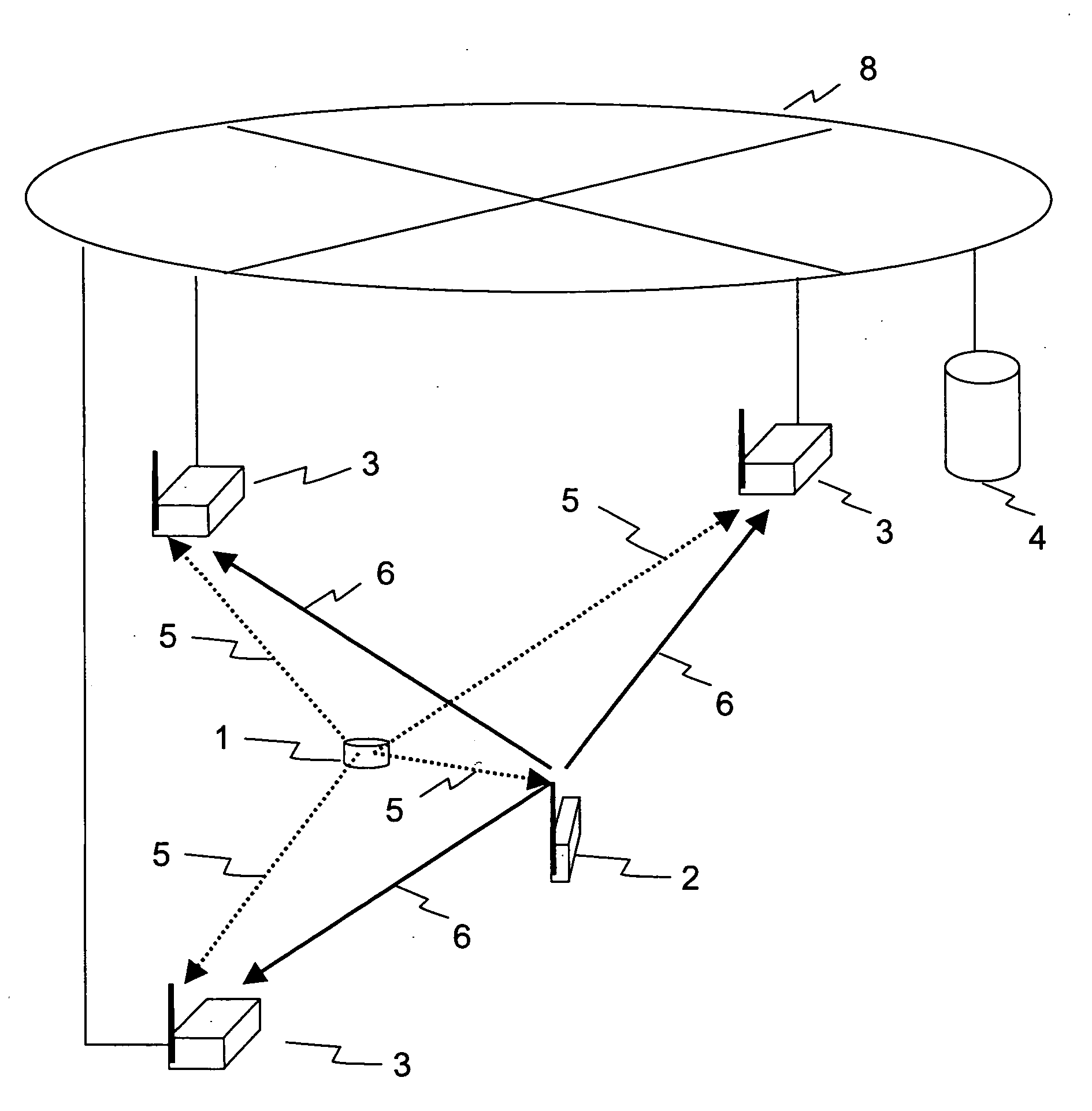
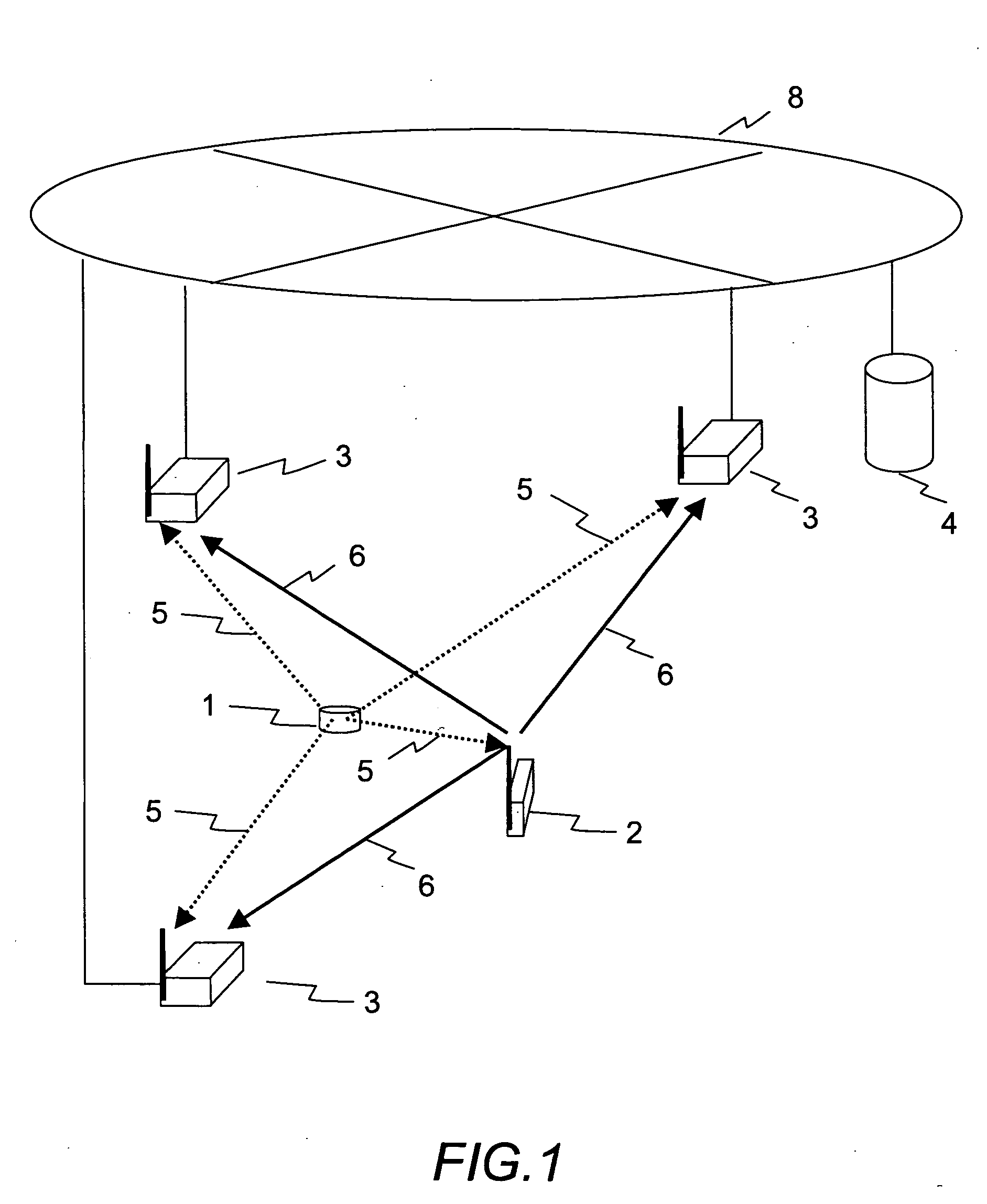
[0028]FIG. 1 is a configuration diagram showing a positioning system according to the first embodiment of the invention.

[0029] A node 1 sends a radio signal (positioning signal) 5 to measure a position. A reference station 2 sends a radio signal (reference signal) 6 to establish a reference time after receiving of the signal from the node 1. An access point (AP) 3 measures reception timings of the positioning signal 5 sent from the node 1 and reception timings of the reference signal 6 sent from the reference station 2. A position calculation server 4 includes a database (not shown) which stores information of coordinates of each access point 3 and a distance from each access point 3 to the reference station 2. The position calculation server 4 is connected to each access point 3 through a network 8. The position calculation server 4 calculates a position of the node 1 by using a result of measureme...

second embodiment

[0084]FIG. 12 is a configuration diagram showing a positioning system according to this invention.

[0085] In FIG. 12, the node 1 includes a transmitter which sends the positioning signal 5. An access point (AP) 40 includes a measuring module which measures a reception timing of the positioning signal 5, and a transmitter which sends the reference signal 6. The position calculation server 4 includes a database which includes a coordinates information of each access point 40. The position calculation server 4 is connected to each access point 40 through a network 8. The position calculation server 4 calculates a position of the node 1 by using a result of the measurement obtained from each access point 40 through the network 8, and the information stored in the database.

[0086] In the second embodiment, the access point 40 that includes a reference signal transmitter and a receiving timing measuring module. The access point 3 that only includes a receiving timing measuring unit may be ...

third embodiment

[0090] As in the case of a third embodiment, when the node 1 that sends a positioning signal includes a transceiver to communicate with the access point 40, the access point 40 with which the node 1 is in communication may be selected as a reference station. And the selected access point 40 alone may send the reference signal 6.

[0091] According to the second embodiment, in addition to the effects of the first embodiment, costs of the system configuration can be reduced since the access points of identical configurations only need be distributed.

[0092]FIG. 13 is a sequential diagram showing a signal transmission process in the positioning system according to a third embodiment of this invention. In third embodiment, the node 1 includes a transceiver to communicate with the access point 3. FIG. 13 shows a case that node 1 receives an instruction from the position calculation server 4, and sends a positioning signal.

[0093] The position calculation server 4 sends a positioning request...


PUM


Abstract

To provide a method of measuring a position of a node by using a radio communication system which comprises the node to send a position measuring signal, and a plurality of base stations to receive radio signals from the node, the method including: the base stations watching signals from the node through a predetermined channel; at least one of the base stations sending a reference signal after receiving of the position measuring signal; at least two of the base stations measuring the reception timing of the position measuring signal and the reception timing of the reference signal; and calculating the position of the node by using the reception timing of the position measuring signal and the reference signal measured by the base stations which have received the reference signal, and position information of the base station which has received the position measuring signal.

Description

CLAIM OF PRIORITY [0001] The present application claims priority from Japanese application P2003-376797 filed on Nov. 6, 2003, the content of which is hereby incorporated by reference into this application. BACKGROUND OF THE INVENTION [0002] This invention relates to a position measuring system including a node which has a radio transmitter and an access point used as a radio base station in the system. [0003] As a representative conventional node position measuring method, there has been available a method of measuring a position by using a signal from a satellite such as a GPS. [0004] As another node position measuring method, there has been available a method of receiving signals sent from a plurality of base stations by a node and calculating a position of the node based on a reception timing difference of the signals. [0005] Specifically, regarding a cellular telephone system, there has been proposed a method of calculating reception timing differences of signals sent from base...

Claims


Application Information

Patent Timeline
Patent Type & Authority Applications(United States)
IPC IPC(8): G01S5/06H04B7/26H04W64/00
CPCH04W64/00
Inventor MIZUGAKI, KENICHIODAKA, TOSHIYUKIMASUI, SHOICHI
Owner HITACHI LTD
Features
  • Generate Ideas
  • Intellectual Property
  • Life Sciences
  • Materials
  • Tech Scout
  • Unparalleled Data Quality
  • Higher Quality Content
  • 60% Fewer Hallucinations
Learn More