Cryogenic air separation process and apparatus

a technology of air separation and air filter, which is applied in the direction of lighting and heating equipment, refrigeration and liquid storage, solidification, etc., can solve the problems of temporary high power rate, high power consumption, and high energy consumption of air separation

Inactive Publication Date: 2005-06-23
LAIR LIQUIDE SA POUR LETUDE & LEXPLOITATION DES PROCEDES GEORGES CLAUDE
View PDF16 Cites 51 Cited by
  • Summary
  • Abstract
  • Description
  • Claims
  • Application Information

AI Technical Summary

Benefits of technology

[0022] c) reducing air feed supplied by the air compressor to maintain the total amount of oxygen contained in the feed streams essentially the same;

Problems solved by technology

Air separation is a very power intensive technology, consuming thousands of kilowatts or several megawatts of electric power to produce large quantities of industrial gases for tonnage applications such as chemicals, refineries, steel mills, etc.
In fact, the electric power is the main operating cost of an air separation plant since its raw material or feedstock is atmospheric air and is essentially free.
This high power usage creates potential shortage and utility companies must allocate other sources of power supply causing temporary high power rate.
However, the cryogenic process of air separation plants is not very flexible since it involves distillation columns and the product specifications require fairly high purities.
Attempts to lower the plant output in a very short time or to increase the plant production quickly to meet product demand can have detrimental effects over plant stability and product integrity.
However, none of the above directly address the aspect of potential savings and economy when adapting the air separation plants to the power rate structure of peak and off-peak periods to obtain cost reduction.
Industry practice also does not resolve the technical problems associated with the adjustment of the air separation units during periods of high power cost and with relatively unchanged product demand.

Method used


Image

  • Cryogenic air separation process and apparatus
  • Cryogenic air separation process and apparatus
  • Cryogenic air separation process and apparatus

Examples


Embodiment Construction

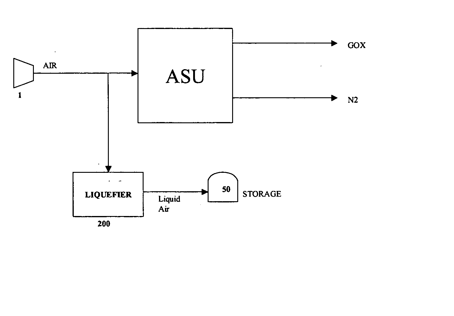
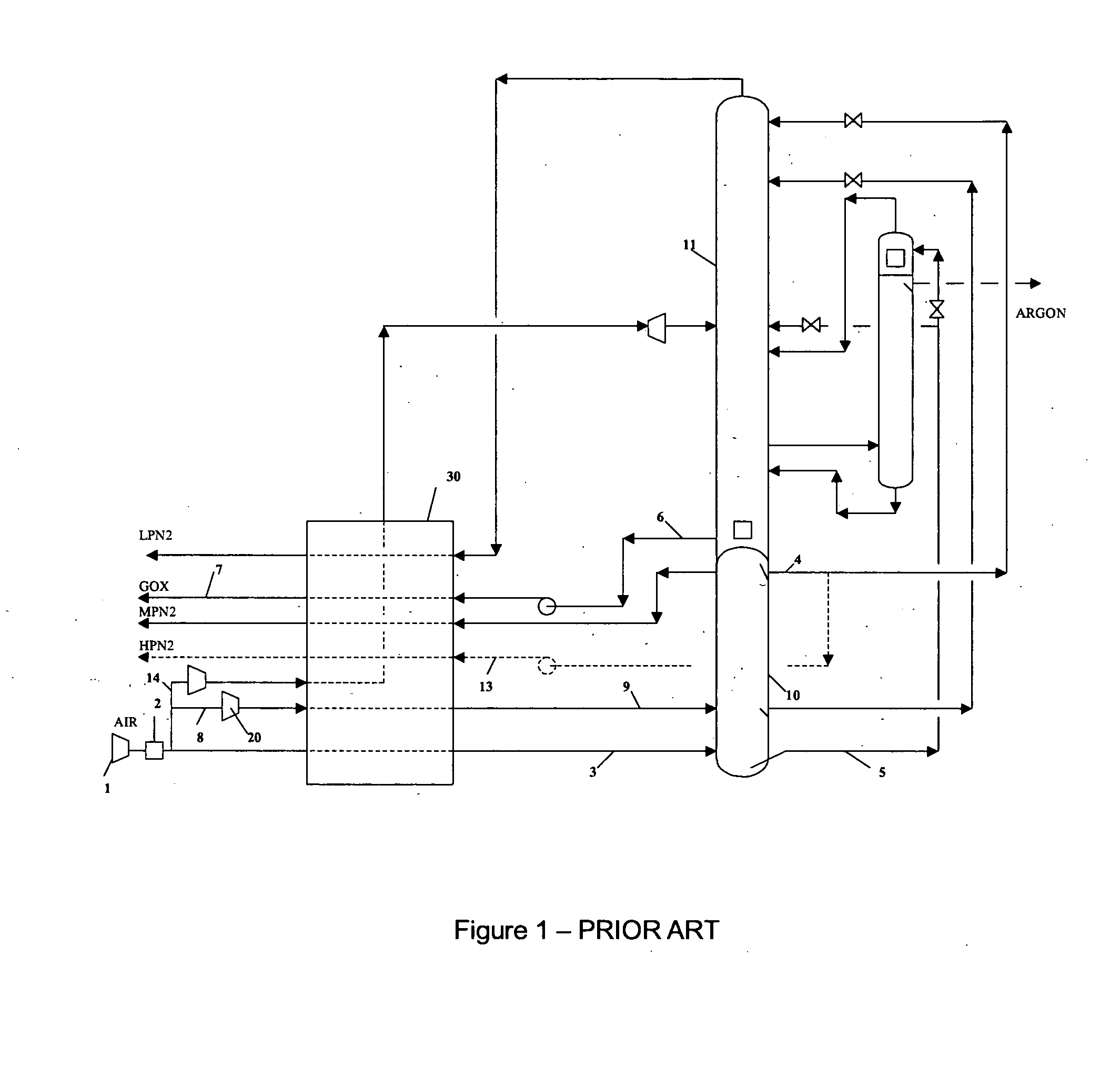
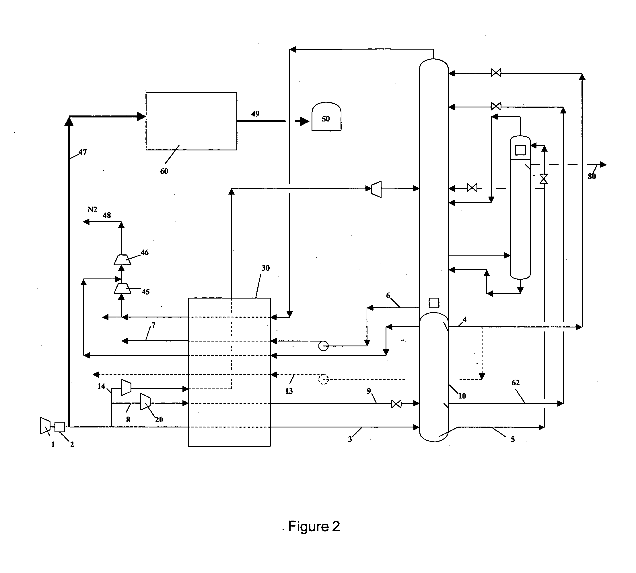
[0041] According to the invention, there is provided a low temperature air separation process for producing pressurized gaseous product in an air separation unit using a system of distillation columns which comprises the following steps: [0042] i) cooling a compressed air stream in a heat exchange line to form a compressed cooled air stream; [0043] ii) sending at least part of the compressed, cooled air stream to a column of the system; [0044] iii) in a first period of time, liquefying a process stream to form a first liquid product and storing at least part of this first liquid product; [0045] iv) in a second period of time, sending the above stored first liquid product to the air separation unit as one of the feed; [0046] v) pressurizing at least one second liquid product stream; [0047] vi) vaporizing the above pressurized second liquid product stream in the heat exchange line to form pressurized gaseous product; and [0048] vii) during the above second period of time, extracting a...


PUM


Abstract

A low temperature air separation process and apparatus for producing pressurized gaseous product in an air separation unit using a system of distillation columns which include cooling a compressed air stream in a heat exchange line to form a compressed cooled air stream, sending at least part of the compressed, cooled air stream to a column of the system, liquefying a process stream to form a first liquid product, storing at least part of the first liquid product in a storage tank, sending at least part of the above first liquid product from the storage tank to the air separation unit as one of the feeds, extracting at least one second liquid product stream from a column of the column system and pressurizing the at least one second liquid product stream, vaporizing the above pressurized second liquid product stream to form pressurized gaseous product in the heat exchange line and extracting a cold gas without warming it completely in the heat exchange line.

Description

CROSS REFERENCE TO RELATED APPLICATION [0001] This application claims the benefit of U.S. Provisional Application 60 / 532,219, filed Dec. 23, 2003, and U.S. Non-Provisional Application No. 10 / 798,068, filed Mar. 11, 2004.FIELD OF INVENTION [0002] This invention relates to an air separation process and associated equipment. BACKGROUND OF THE INVENTION [0003] Air separation is a very power intensive technology, consuming thousands of kilowatts or several megawatts of electric power to produce large quantities of industrial gases for tonnage applications such as chemicals, refineries, steel mills, etc. [0004] A typical liquid pumped process is illustrated in FIG. 1. In this type of process, atmospheric air is compressed by a Main Air Compressor (MAC) 1 to a pressure of about 6 bar absolute, it is then purified in an adsorber system 2 to remove impurities such as moisture and carbon dioxide that can freeze at cryogenic temperature to yield a purified feed air. A portion 3 of this purifie...

Claims


Application Information

Patent Timeline
Patent Type & Authority Applications(United States)
IPC IPC(8): F25J1/00F25J1/02F25J3/00F25J3/04
CPCF25J1/0012F25J2210/50F25J1/0234F25J1/0251F25J3/04054F25J3/0406F25J3/04084F25J3/0409F25J3/04224F25J3/04254F25J3/04266F25J3/0429F25J3/04303F25J3/04339F25J3/04345F25J3/04351F25J3/04412F25J3/04496F25J3/04545F25J3/04575F25J3/04581F25J3/04593F25J3/04606F25J3/04678F25J2210/40F25J2210/62F25J2215/02F25J2215/40F25J2245/40F25J2245/42F25J3/04836F25J2210/42F25J1/0221
Inventor BRUGEROLLE, JEAN-RENAUDHA, BAO
Owner LAIR LIQUIDE SA POUR LETUDE & LEXPLOITATION DES PROCEDES GEORGES CLAUDE
Why Eureka
Try Eureka