Measurement, compensation and control of equivalent shear rate in acoustic wave sensors

a technology of acoustic waves and sensors, applied in the field of acoustic waves, can solve the problems of limiting utility and reliability, difficult to successfully apply process control or operate on moving platforms, and affecting the accuracy of acoustic waves,

Inactive Publication Date: 2005-06-23
VECTRON INT INC
View PDF9 Cites 14 Cited by
  • Summary
  • Abstract
  • Description
  • Claims
  • Application Information

AI Technical Summary

Benefits of technology

[0027] In the preferred embodiment the step of measuring viscosity is performed utilizing the acoustic wave device, and more preferably by calculating power insertion loss between the input and output transducers, or calculating what is known as the change in ‘acoustic impedance’ of the transducer. In the preferred embodiments, the selected region above contains therewith the geometrical midpoint between the input transducer and output transducer respective geometries.
[0028] In other embodiments, the step of measuring viscosity is carried out by measuring phase shift of the imparted signal or measuring the frequency change required for maintaining a constant phase shift of the imparted signal.

Problems solved by technology

While this method is widely used and highly accurate, it is difficult to successfully apply to process control or to operate on moving platforms.
The ability to accurately measure nonlinearities of viscosity as a function of rotational rate notwithstanding, the use of moving parts limits utility and reliability.
An ideal liquid, having neither shear elasticity nor viscosity, cannot support a shear sound wave.
Viscous liquids can support a shear sound wave; however the wave decays as it travels and is only able to travel a few wavelengths before being totally damped out by frictional losses.
While this method enjoys widespread use and there exist numerous clever methods of automating sample injection and measurement, the approach is not without its problems and the industry is in need of alternative solutions.
A principal problem with this method is the discontinuous and sampled nature of the measurement, in which it is typically performed off-line in a laboratory separate from the process being monitored and controlled.
Other drawbacks are the size of the apparatus and its susceptibility to vibration and orientation of the capillary.
The method is not employed due to the substantial variations in the size of a wavelength with changes in viscosity and the significant signal to noise ratio issues associated with measuring the phase velocity of a heavily damped wave over a small number of acoustic wavelengths.
The method suffers constraints of fixed geometry between the transducers that sometimes does not fit the flow requirements within a process, and as the Farone patent discloses only measurement of the phase difference between the longitudinal and shear wave without consideration of the amplitude or attenuation of the wave, it suffers from operating under certain meaningful, but unknown operating conditions, such as the signal amplitude, which are known to change the measured quantity.
This limitation is specifically important in liquids that exhibit non-linear viscosity response to shear rate.
This method has been plagued by poor reproducibility when used with affordable instrumentation, primarily due to the lack of a differential measurement.
In all of the acoustic wave methods, it has generally been virtually impossible to correlate the “shear rate” at which the measurement occurs to the “shear rate” of such reference methods as the rotating spindle or the capillary tube.
Therefore, while the acoustic wave methods are structurally superior, having no moving parts and offering continuous in situ measurement, they are not widely accepted due to the unknown conditions under which the measurements occur.
This is, unfortunately not the case, and all liquids exhibit nonlinearity beyond a given stress limit or shear rate limit.
While many liquids exhibit behaviors consistent with this model at relatively low frequencies and amplitudes, this has been found to be an erroneous assumption in general.
The most significant error to result from this assumption is to equate the shear rate of the sensor with the frequency of the harmonic motion.
Therefore a promising class of sensors for measuring viscosity or for measuring chemical processes that induce a change in viscosity are underutilized by the industry, primarily because those sensors do not provide for measurement or control of the shear rate at which the viscosity is being measured.
It is further found that this class of sensors are being underutilized because it is not presently possible to maintain a constant shear rate in the sensor over a range of viscosities or to reproducibly alter the shear rate of the measurement over a desired range in a given sample.

Method used


Image

  • Measurement, compensation and control of equivalent shear rate in acoustic wave sensors
  • Measurement, compensation and control of equivalent shear rate in acoustic wave sensors
  • Measurement, compensation and control of equivalent shear rate in acoustic wave sensors

Examples


Embodiment Construction

[0084] In these specifications, an acoustic wave device is considered a device comprising a crystalline material having a plurality of electrodes, and that in response to electrical power presented between at least a pair of these electrodes, provides a corresponding movement of the crystal face, and conversely, generates an electrical signal in the electrodes in response to power applied to the crystal face.

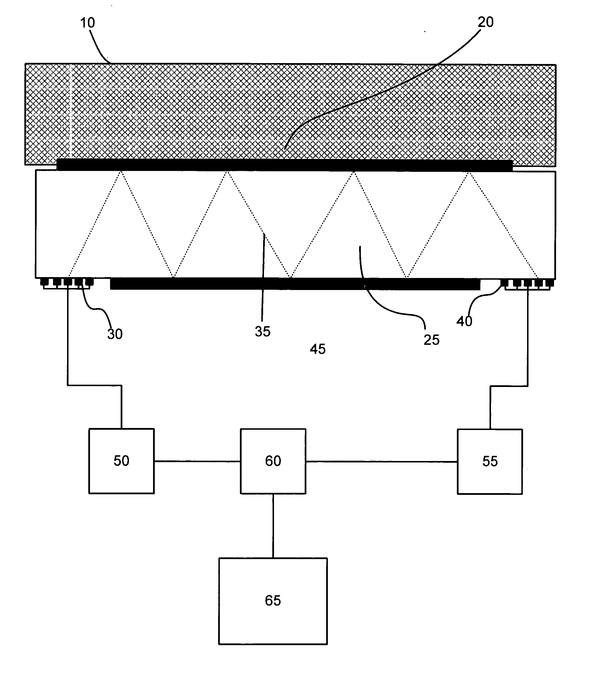
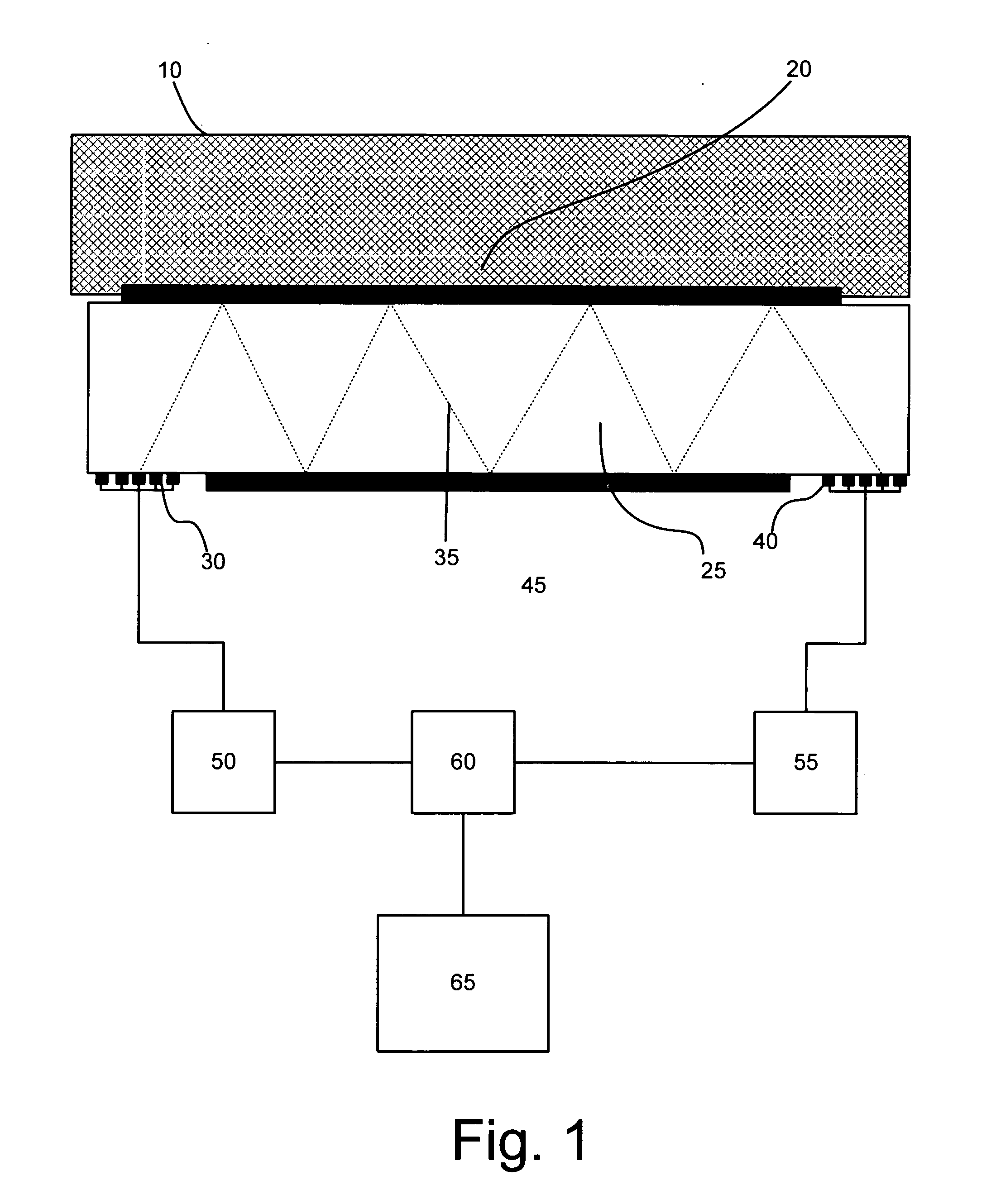
[0085] The preferred embodiment utilizes a known method for viscosity measurement, comprising an acoustic wave device comprising a piezoelectric crystal 25, with an input 30 and output 40 transducers coupled to it. The input transducer is coupled to a power source 50, which injects a harmonic signal of known power level and frequency. The energy coupled to the input transducer causes an acoustic wave 35 to travel in the crystal, and impart a wave to the fluid 10. Since energy is transferred to the fluid 10, the level of power that arrives at the output transducer 40 is lower th...


PUM

PropertyMeasurementUnit
shear rateaaaaaaaaaa
viscosityaaaaaaaaaa
frequencyaaaaaaaaaa

Abstract

A method for measuring viscosity and shear rate at which the measurement is performed is provided, by utilizing an acoustic wave sensor, and calculating the shear rate as a function of the characteristic rate of quartz movement in response to a given power transmitted to a fluid, and the viscosity of the fluid. Related aspects of the invention provide for methods for controlling the shear rate at which a viscosity measurement is performed, and characterizing viscoelastic fluids at a plurality of shear rates.

Description

FIELD OF THE INVENTION [0001] This application is directed generally to acoustic wave sensors employing sound waves to measure viscoelastic properties of a material, and more particularly to methods of relating viscosity measurements to the shear rate at which such measurements are performed. BACKGROUND OF THE INVENTION [0002] Viscosity, and more generally, viscoelasticity, are properties of liquids and solids that relate the shear forces generated by or applied to a material to the amount of shear deformation or flow. While the invention applies equally well to viscoelasticity, the present discussion will be limited to viscosity measurement for simplicity. Viscosity is of widespread interest in many manufacturing environments and is measured as a primary quality of some products and as a secondary quality (a means of monitoring process state) in other processes. [0003] Viscosity describes the force required in order to make successive molecular layers of a liquid move past each oth...

Claims


Application Information

Patent Timeline
Patent Type & Authority Applications(United States)
IPC IPC(8): G01N11/16G01N29/02G01N29/22
CPCG01N11/16G01N29/022G01N29/222G01N2291/0422G01N2291/02818G01N2291/02827G01N2291/0421G01N2291/0256
Inventor ANDLE, JEFFREY C.
Owner VECTRON INT INC
Why Eureka
Try Eureka