Compensation of spacing between magnetron and sputter target
a technology of magnetron and sputter target, applied in the field of moving magnetron, can solve the problems of affecting the magnetic enhancement of sputtering, presenting several problems, and the approach does not address the erosion of the target, so as to achieve a stable sputtering process and a constant magnetic field
- Summary
- Abstract
- Description
- Claims
- Application Information
AI Technical Summary
Benefits of technology
Problems solved by technology
Method used
Image
Examples
first embodiment
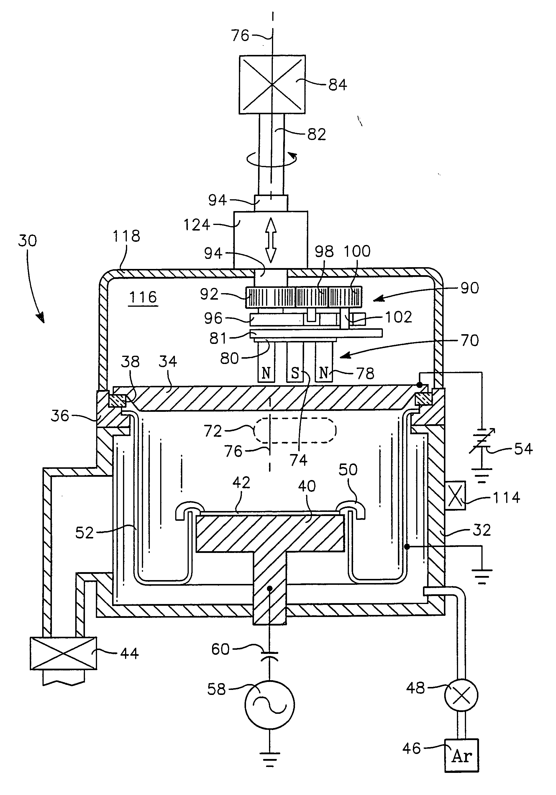
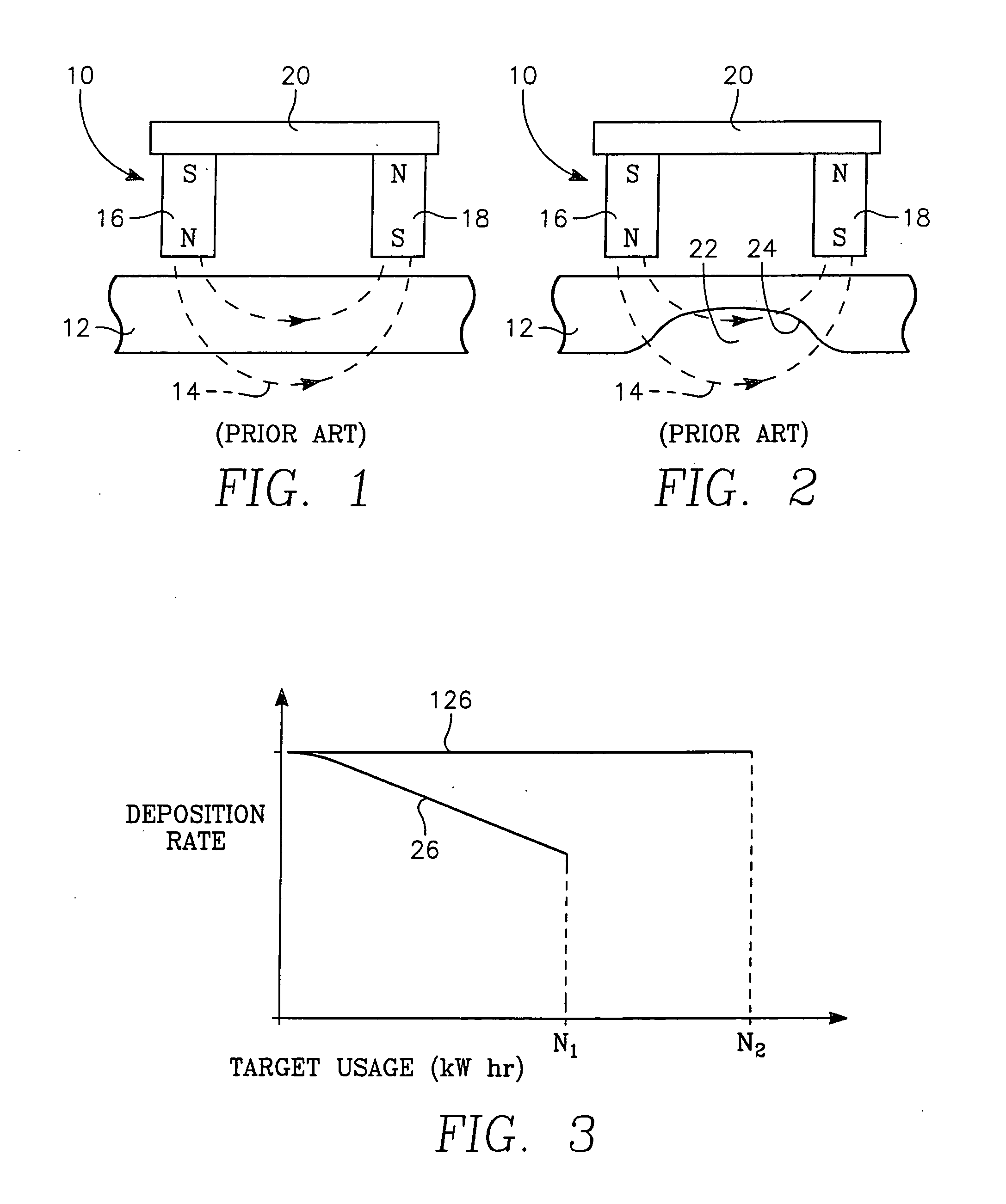
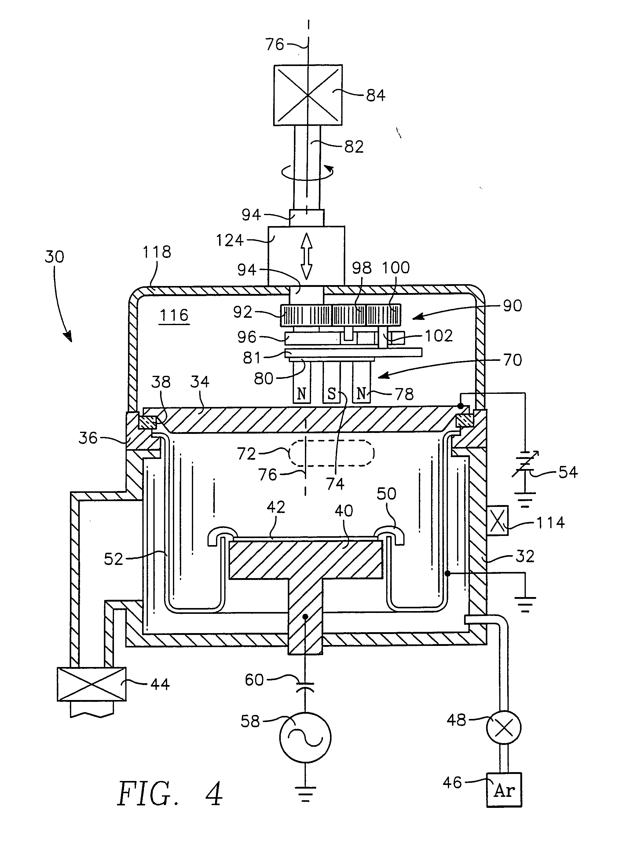
[0042] the invention used to verify the effects of compensating the magnetron-to-target spacing uses a series of shims of varying thickness placed between the magnetron 70 of FIG. 5 and the carrier 81. As the target erodes, the previous shim is replaced by a thinner shim. As a result, the magnetron 70 is being moved away from the back of the target 34 along a single axis at the center of the magnetron 70 although that axis is moving as the magnetron 70 is moved along a planetary path. As a result, a nearly constant magnetic field can be maintained at the sputtering surface of the target 34 over the target life thereby stabilizing the sputtering process. The manual shimming process may be alternatively effected by shims placed between the otherwise stationary housing 94 and the roof of the tank 118.
[0043] Actual experimental data using a copper target and a planetary magnetron in the reactor of FIG. 4 are presented in FIG. 9. Plot 125 shows the magnet-to-target (MTS) spacing, specifi...
second embodiment
[0054] a rotational lift drive includes a lead screw mechanism 200 illustrated in the orthographic, partially sectioned view of FIG. 12. A support collar 202 is fixed to the tank roof 142 and rotatably supports the lead nut 150 through a ring bearing 204 trapped by an upper retainer ring 206. A lead nut lever 208 extends radially outwardly from the lead nut 150 and has two parallel arms 210 formed at its end. A pivot connection including two arms 212 at the back of the lift motor 176, an unillustrated pivot pin through them, and a mount for the pin, pivotally mounts the lift motor 176 to the tank roof 142 in a horizontal orientation. The horizontally oriented lift motor 176 rotates a shaft 216 having a lead screw formed on its distal end. A nut box 220 threadably captures the lead screw of the drive shaft 216 and is pivotally supported by a pin 218 fixed to the arms 210 of the lead nut lever 208. Thereby, rotation of the lift motor 176 rotates the lead nut 150 to raise or lower alon...
PUM
| Property | Measurement | Unit |
|---|---|---|
| Magnetic field | aaaaa | aaaaa |
| Depth | aaaaa | aaaaa |
| Erosion-corrosion rate | aaaaa | aaaaa |
Abstract
Description
Claims
Application Information
 - R&D
- Intellectual Property
- Life Sciences
- Materials
- Tech Scout
- Unparalleled Data Quality
- Higher Quality Content
- 60% Fewer Hallucinations
Browse by: Latest US Patents, China's latest patents, Technical Efficacy Thesaurus, Application Domain, Technology Topic, Popular Technical Reports.
© 2025 PatSnap. All rights reserved.Legal|Privacy policy|Modern Slavery Act Transparency Statement|Sitemap|About US| Contact US: help@patsnap.com


