Mechanism for varying the spacing between sputter magnetron and target

a technology of magnetron and target, which is applied in the direction of electrolysis components, vacuum evaporation coatings, coatings, etc., can solve the problems of affecting the magnetic enhancement of sputtering, presenting several problems, and the approach does not address the erosion of target sputtering, so as to achieve a stable sputtering process and a constant magnetic field

Active Publication Date: 2005-06-23
APPLIED MATERIALS INC
View PDF27 Cites 43 Cited by
  • Summary
  • Abstract
  • Description
  • Claims
  • Application Information

AI Technical Summary

Benefits of technology

[0019] The invention includes the method and apparatus for compensating erosion of a plasma sputtering target by moving the magnetron away from the back of the target as the front of the

Problems solved by technology

However, the emphasis has recently changed in the use of sputtering for the fabrication of integrated circuits because vertical interconnects through inter-level dielectrics having the high aspect ratios now being used present a much greater challenge than the horizontal interconnects.
The target erosion presents several problems if the lifetime of the target 12 is to be maximized.
These approaches do not address how the erosion affects the magnetic enhancement of sputtering.
Secondly, the concentrated magnetic field of the small magnetron increases the plasma density adjacent the portion of the target being sputtered, thereby increasing the ionization fraction of the target atoms being sputtered.
However, the target erosion affects the effective magnetic field at the target face being sputtered, thereby changing the sputtering rate and the ionization fraction.
Thirdly, the small magnetron makes uniform target sputtering that much more difficult.
Various magnetron shapes, e.g., triangular have been used to increase the uniformity of sputtering, but their uniformity is not complete.
Secondly, the non-uniformity of sputtering reduces the lifetime of the target to a number N1 at which the erosion trough maximum approaches the t

Method used


Image

  • Mechanism for varying the spacing between sputter magnetron and target
  • Mechanism for varying the spacing between sputter magnetron and target
  • Mechanism for varying the spacing between sputter magnetron and target

Examples


first embodiment

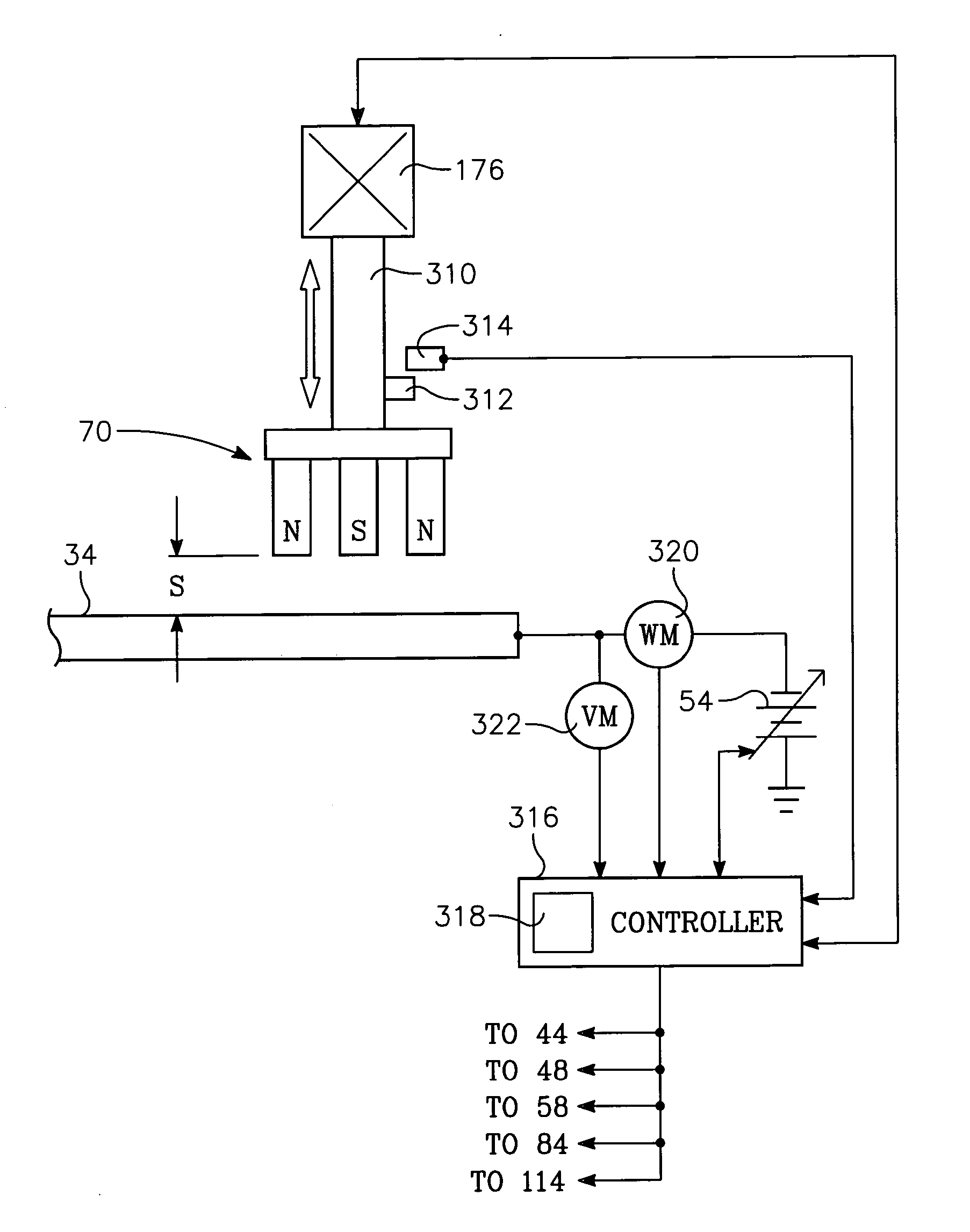
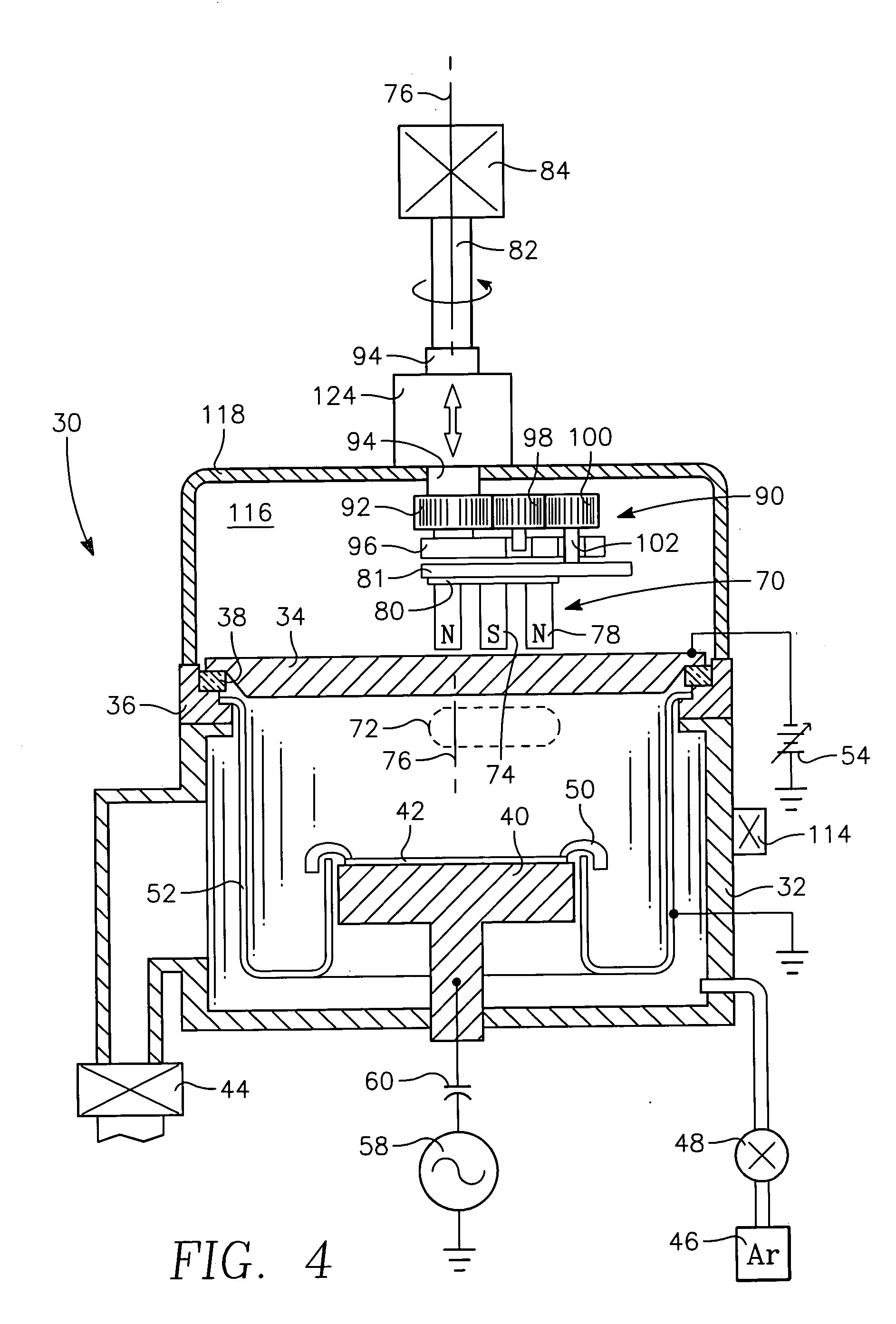
[0042] the invention used to verify the effects of compensating the magnetron-to-target spacing uses a series of shims of varying thickness placed between the magnetron 70 of FIG. 5 and the carrier 81. As the target erodes, the previous shim is replaced by a thinner shim. As a result, the magnetron 70 is being moved away from the back of the target 34 along a single axis at the center of the magnetron 70 although that axis is moving as the magnetron 70 is moved along a planetary path. As a result, a nearly constant magnetic field can be maintained at the sputtering surface of the target 34 over the target life thereby stabilizing the sputtering process. The manual shimming process may be alternatively effected by shims placed between the otherwise stationary housing 94 and the roof of the tank 118.

[0043] Actual experimental data using a copper target and a planetary magnetron in the reactor of FIG. 4 are presented in FIG. 9. Plot 125 shows the magnet-to-target (MTS) spacing, specifi...

second embodiment

[0054] a rotational lift drive includes a lead screw mechanism 200 illustrated in the orthographic, partially sectioned view of FIG. 12. A support collar 202 is fixed to the tank roof 142 and rotatably supports the lead nut 150 through a ring bearing 204 trapped by an upper retainer ring 206. A lead nut lever 208 extends radially outwardly from the lead nut 150 and has two parallel arms 210 formed at its end. A pivot connection including two arms 212 at the back of the lift motor 176, an unillustrated pivot pin through them, and a mount for the pin, pivotally mounts the lift motor 176 to the tank roof 142 in a horizontal orientation. The horizontally oriented lift motor 176 rotates a shaft 216 having a lead screw formed on its distal end. A nut box 220 threadably captures the lead screw of the drive shaft 216 and is pivotally supported by a pin 218 fixed to the arms 210 of the lead nut lever 208. Thereby, rotation of the lift motor 176 rotates the lead nut 150 to raise or lower alon...


PUM

PropertyMeasurementUnit
Distanceaaaaaaaaaa

Abstract

A lift mechanism for and a corresponding use of a magnetron in a plasma sputter reactor. A magnetron rotating about the target axis is controllably lifted away from the back of the target to compensate for sputter erosion, thereby maintaining a constant magnetic field and resultant plasma density at the sputtered surface, which is particularly important for stable operation with a small magnetron, for example, one executing circular or planetary motion about the target axis. The lift mechanism can include a lead screw axially fixed to the magnetron support shaft and a lead nut engaged therewith to raise the magnetron as the lead nut is turned. Alternatively, the support shaft is axially fixed to a vertically moving slider. The amount of lift may be controlled according a recipe based on accumulated power applied to the target or by monitoring electrical characteristics of the target.

Description

RELATED APPLICATIONS [0001] This application claims benefit of U.S. provisional application Ser. No. 60 / 529,209, filed Dec. 12, 2003. It also is related to concurrently filed U.S. patent application entitled COMPENSATION OF SPACING BETWEEN MAGNETRON AND SPUTTER TARGET.FIELD OF THE INVENTION [0002] The invention relates generally to sputter deposition of materials. In particular, the invention relates to a movable magnetron that creates a magnetic field to enhance sputtering. BACKGROUND ART [0003] Sputtering, alternatively called physical vapor deposition (PVD), is the most prevalent method of depositing layers of metals and related materials in the fabrication of integrated circuits. The more conventional type of sputtering, as originally applied to integrated circuits as well as to other applications, deposits upon a workpiece a planar layer of the material of the target. However, the emphasis has recently changed in the use of sputtering for the fabrication of integrated circuits ...

Claims


Application Information

Patent Timeline
IPC IPC(8): C23C14/32C23C14/34C23C14/35C23C14/54H01J37/34
CPCC23C14/3407C23C14/35H01J37/3455H01J37/3408C23C14/54C23C14/34
Inventor HONG, ILYOUNG RICHARDYOUNG, DONNYROSENSTEIN, MICHAELLOWRANCE, ROBERT B.LUBBEN, DANIEL C.MILLER, MICHAEL ANDREWDING, PEIJUNSANKARANARAYAN, SREEKRISHNANYOSHIDOME, GOICHI
Owner APPLIED MATERIALS INC
Why Eureka
Try Eureka