Method and device for removing metallic material of a workpiece

a technology of workpieces and metallic materials, which is applied in the direction of machining electric circuits, manufacturing tools, electric circuits, etc., can solve the problems of inability to manufacture injectors with a complex spray orifice geometry using conventional methods, relatively high production costs, and considerable wear

Inactive Publication Date: 2005-06-23
ROBERT BOSCH GMBH
View PDF3 Cites 19 Cited by
  • Summary
  • Abstract
  • Description
  • Claims
  • Application Information

AI Technical Summary

Benefits of technology

[0023] Therefore, the present invention allows a variable amount of material to be removed inside or along the wall of a hole, using the current of the ECM process and / or the speed of the relative movement between the workpiece and the electrode and / or the structural shape of the electrode. All of these measures influence the geometry of the machined workpiece both quantitatively and qualitatively. Consequently, hollows, in particular, may also be produced inside a hole.
[0024] Producing a removal geometry with the aid of the ECM process according to the present invention is substantially better than producing it with the aid of corrosive machining according to the related art. The electrode for the ECM process is not subjected to any wear.

Problems solved by technology

Electrodes for such erosive machining processes (EDM) are relatively expensive to produce and are subjected to considerable wear during the EDM boring process.
Against this background, injectors having a complex spray orifice geometry may not be manufactured using conventional methods such as erosive machining, laser drilling, microgalvanic drilling, and the like, or may only be manufactured at great expense using the conventional methods.

Method used


Image

  • Method and device for removing metallic material of a workpiece
  • Method and device for removing metallic material of a workpiece
  • Method and device for removing metallic material of a workpiece

Examples


Embodiment Construction

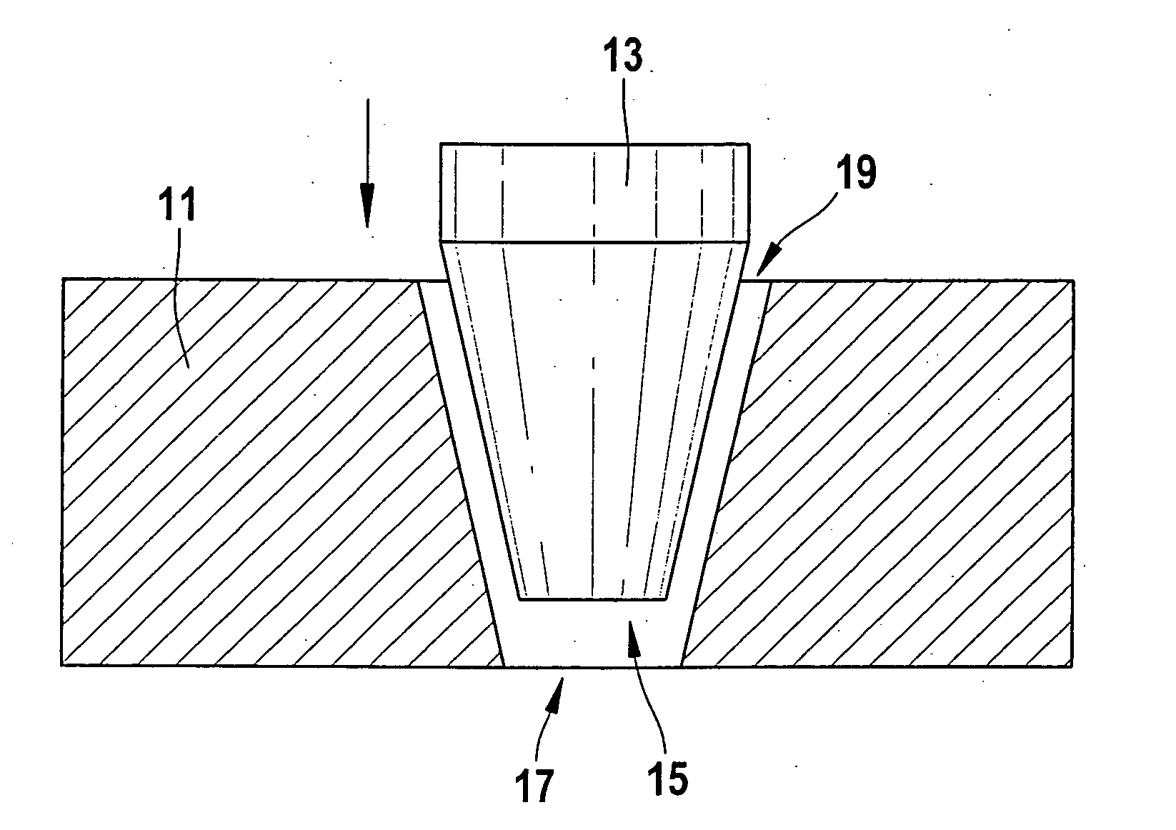
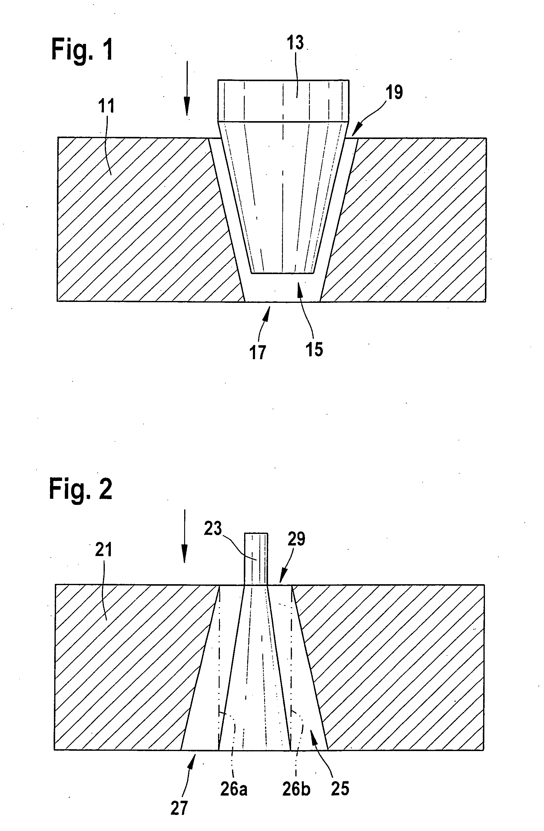
[0034]FIG. 1 shows a workpiece 11 having a hole 15 that includes a first opening 19 and a second opening 17, as well as an electrode 13 that is conically shaped at its tip. To execute the method of the present invention, electrode 13 is moved in the direction of the arrow.

[0035] Conical spray orifice 15 is produced from the end of first opening 19 (large spray-orifice diameter), using the ECM-sinking machining of the present invention. In this variant, the shape of hole 15 is influenced by the shape of electrode 13.

[0036]FIG. 2 shows a workpiece 21 having a hole 25 that includes a first opening 29 and a second opening 27, as well as an electrode 23 that is moved in the direction of the arrow to implement the method of the present invention.

[0037] A conical spray orifice 15 is produced in FIG. 2, just as in FIG. 1. In this case, the machining is carried out from the end of opening 27 having the small spray-aperture diameter. In this connection, a cylindrical hole delimited by dash...


PUM

PropertyMeasurementUnit
metallicaaaaaaaaaa
currentaaaaaaaaaa
voltageaaaaaaaaaa

Abstract

A method for removing metallic material of a workpiece, using the flow of current between an electrode and the workpiece in the presence of an electrolyte. In this context, a relative movement occurs between the electrode and the workpiece as a function of time. In addition, it is provided that at least one further process parameter be regulated and/or changed as a function of time.

Description

FIELD OF INVENTION [0001] The present invention relates to a method for removing metallic material of a workpiece and a device for implementing the method. BACKGROUND INFORMATION [0002] Electrochemical methods, inter alia, are used for machining or patterning surfaces of metallic workpieces. These so-called electrochemical machining processes (ECM) are based on removing metallic material of the workpiece surface to be patterned. To this end, the workpiece is wired as an anode and dipped into an electrolyte solution. A sufficiently high voltage is applied, i.e., a sufficiently large current is conducted, between the workpiece that is contacted as an anode and an electrode taking the form of a separate cathode. These measures allow material to be removed at the workpiece. [0003] Until now, such ECM processes have been predominantly used for patterning or fine-patterning surfaces, which have optionally been roughly pre-patterned with the aid of a different removal method. [0004] Europe...

Claims


Application Information

Patent Timeline
Patent Type & Authority Applications(United States)
IPC IPC(8): B23H3/02B23H9/16
CPCB23H9/16B23H3/02
Inventor GLOCK, ARMINHACKENBERG, JUERGEN
Owner ROBERT BOSCH GMBH
Why Eureka
Try Eureka