Bipolar plate fabrication by roll bonding

Active Publication Date: 2005-06-23
GM GLOBAL TECH OPERATIONS LLC
View PDF12 Cites 32 Cited by
  • Summary
  • Abstract
  • Description
  • Claims
  • Application Information

AI Technical Summary

Problems solved by technology

Stamping however is unfavorable because it subjects the sheets to high strains and distortion.
In addition, joining stamped structures may be complicated.
First, after stamping, there is minimal sheet to sheet contact between flow channels, thus, alignment and weld containment are difficult.
Secondly, access for joining between the flow channels is obstructed by the flow channel structure.
These too, however, present unfavorable drawbacks.
Brazing of austenitic stainless steel has been successful, but is costly.
The cost is par

Method used


Image

  • Bipolar plate fabrication by roll bonding
  • Bipolar plate fabrication by roll bonding
  • Bipolar plate fabrication by roll bonding

Examples


Embodiment Construction

[0017] The following description of the preferred embodiment is merely exemplary in nature and is in no way intended to limit the invention, its application, or uses. For purposes of clarity, the same reference numbers will be used in the drawings to identify similar elements.

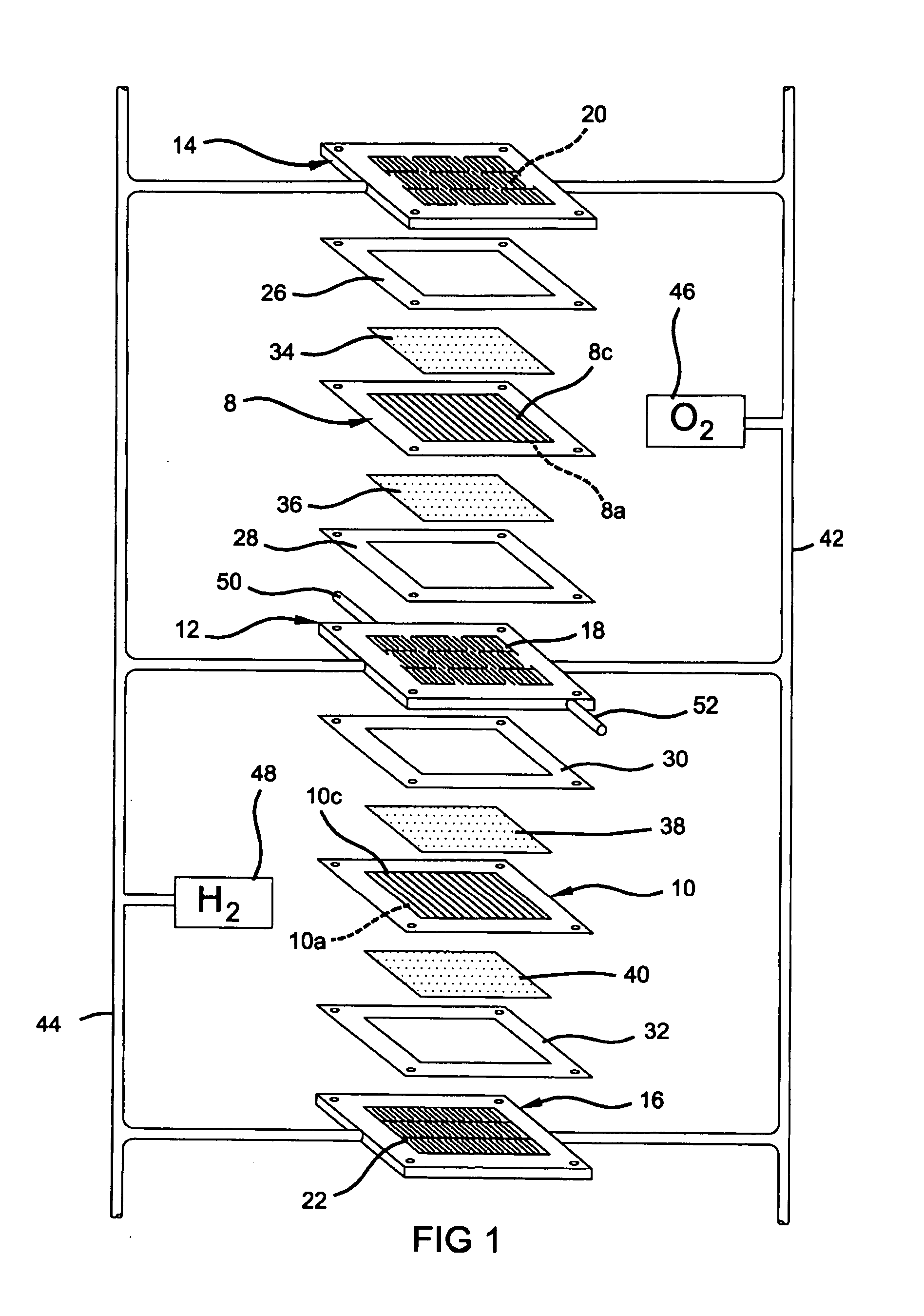
[0018]FIG. 1 schematically depicts a partial PEM fuel cell stack having a pair of membrane-electrode-assemblies (MEAs) 8 and 10 separated from each other by a non-porous, electrically-conductive bipolar plate 12. Each of the MEAs 8, 10 have a cathode face 8c, 10c and an anode face 8a, 10a. The MEAs 8 and 10, and bipolar plate 12, are stacked together between non-porous, electrically-conductive, liquid-cooled bipolar plates 14 and 16. The bipolar plates 12, 14 and 16 each include flow fields 18, 20 and 22 having a plurality of flow channels formed in the faces of the plates for distributing fuel and oxidant gases (e.g., H2 and O2) to the reactive faces of the MEAs 8 and 10. Nonconductive gaskets or seals 26, 28...


PUM

PropertyMeasurementUnit
Thicknessaaaaaaaaaa
Forceaaaaaaaaaa
Flow rateaaaaaaaaaa

Abstract

An anti-bonding material is placed in a desired pattern onto a first sheet of conductive material. A second sheet of conductive material is roll bonded with the first sheet of material. Fluid is injected between the bonded first and second sheets of material to expand the sheets of material at the desired pattern. A flow channel is formed at the desired pattern between the first and second sheet during fluid injection.

Description

FIELD OF THE INVENTION [0001] The present invention relates to bipolar plates, and more particularly to a method of making a bipolar plate using roll bonding. BACKGROUND OF THE INVENTION [0002] Current collector plates or bipolar plates are an integral part of the fuel cell stack. Current collector plates function in a fuel cell stack as fluid distribution elements and function as bipolar plates to separate MEAs from one another. Each plate assembly is typically constructed of thin gauge metal sheets such as stainless steel coated with a conductive coating. Generally, two adjacent metal sheets are joined together forming a conductive heat exchanger. The joined plate assembly has internal flow channels along its length for coolant flow. Channels on either side of the bipolar plate serve as distribution pathways for fuel and oxidant gas to adjacent current collectors. A hermetic seal is required around the perimeter of the joined plates to prevent mixing of the coolant, fuel, oxidant ...

Claims


Application Information

Patent Timeline
IPC IPC(8): B21D53/04B23K20/10B23K20/18
CPCB21D53/045Y10T29/49371B23K20/18B23K20/103
Inventor GAYDEN, XIAOHONGCHEN, YEN -LUNGSIGLER, DAVID R.
Owner GM GLOBAL TECH OPERATIONS LLC
Why Eureka
Try Eureka