Motor

a technology for motors and motor parts, applied in the field of motors, can solve the problems of increasing the number of components and the corresponding cost, and ensuring such sufficient space on the circuit board, so as to improve the productivity of the motor, reduce the cost, and simplify the manufacturing process

Inactive Publication Date: 2005-06-23
NIPPON DENSAN CORP
View PDF8 Cites 4 Cited by
  • Summary
  • Abstract
  • Description
  • Claims
  • Application Information

AI Technical Summary

Benefits of technology

[0018] An object of the present invention is to provide a motor having an advantage for cost reduc

Problems solved by technology

However, in some products, it may be difficult to ensure such sufficient space on the circuit b

Method used


Image

  • Motor
  • Motor
  • Motor

Examples


Embodiment Construction

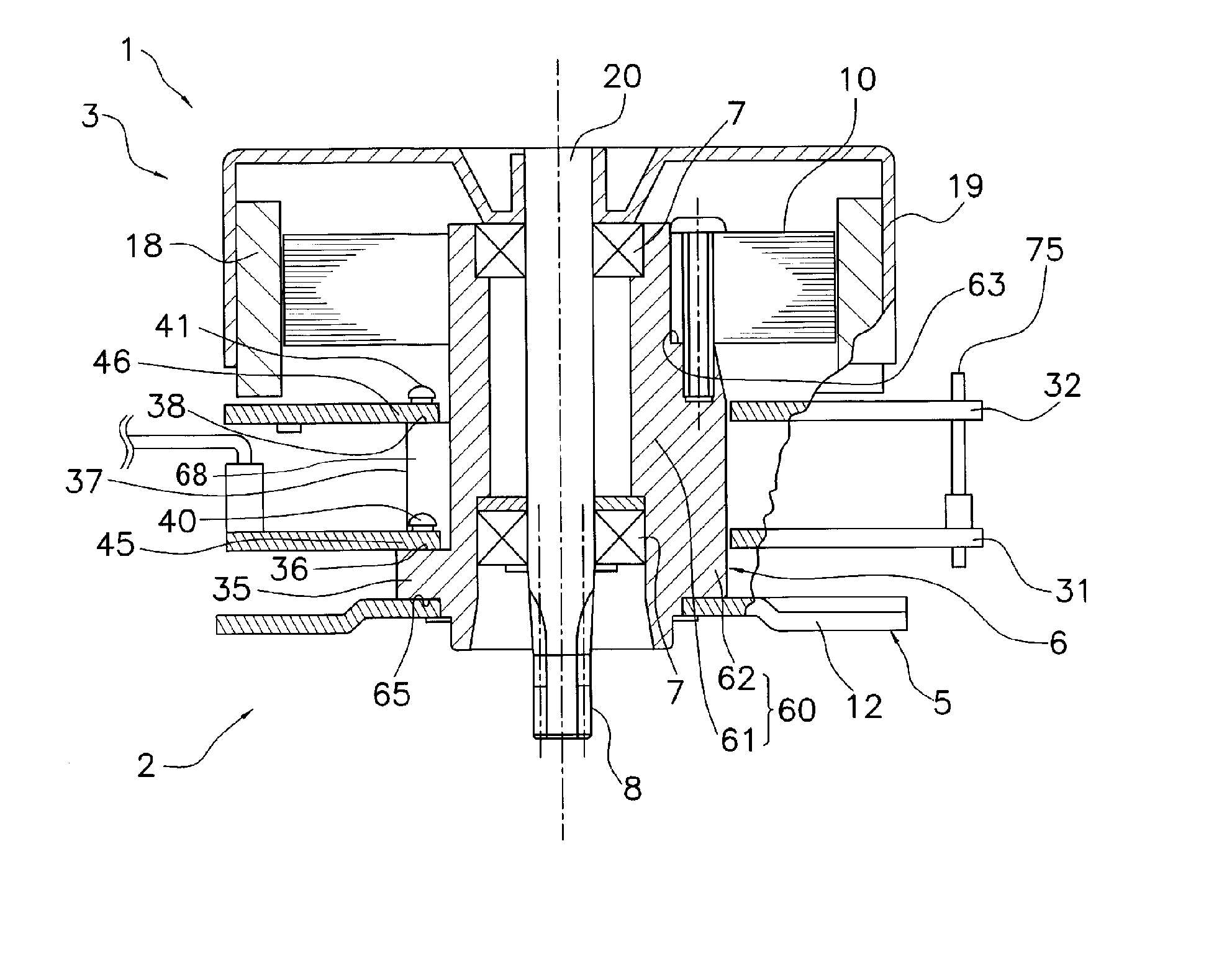
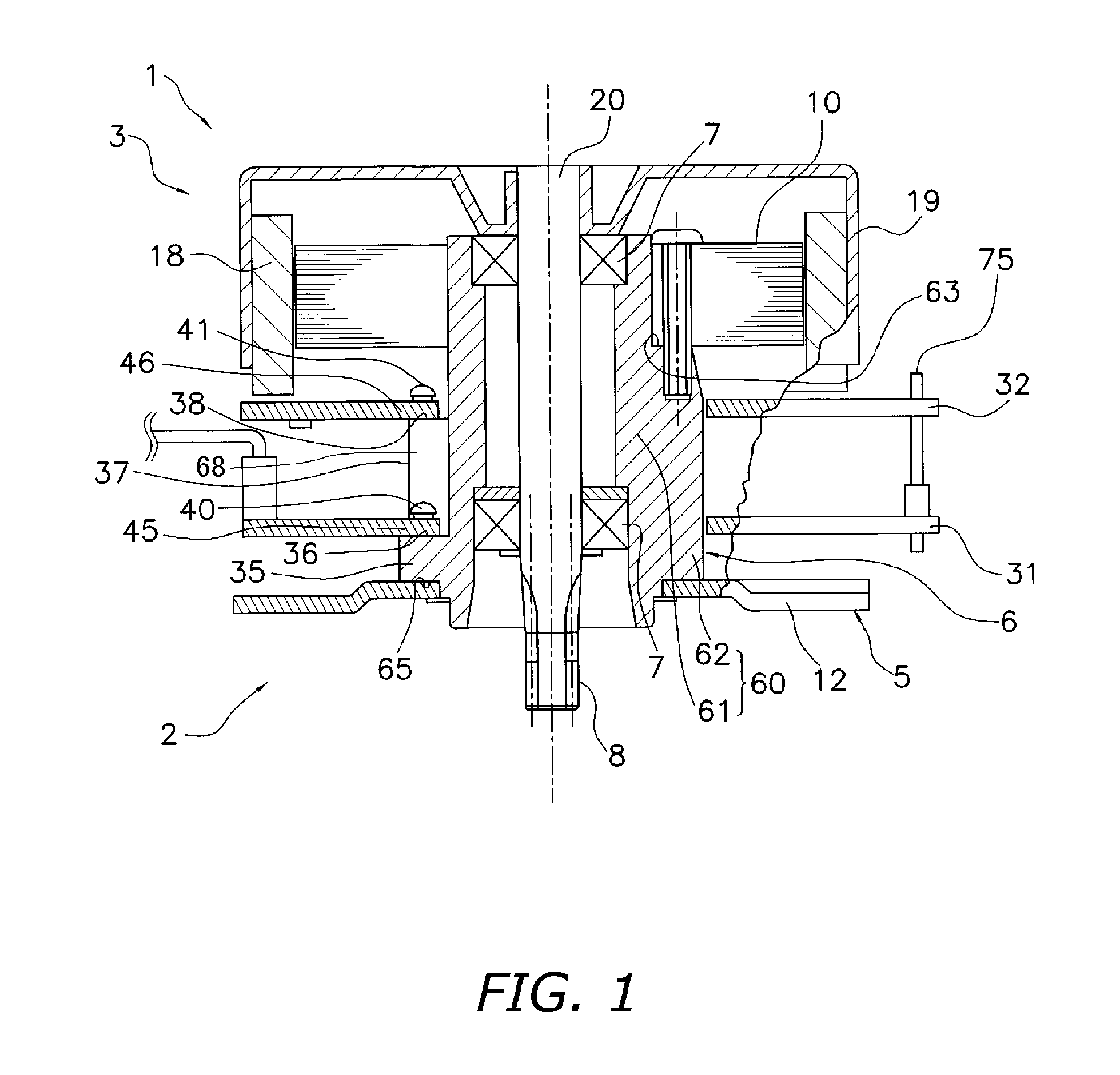
[0030] A motor in accordance with an embodiment of the present invention will be described with reference to FIG. 1 to FIG. 7.

[0031] Configuration—FIG. 1 is a cross-sectional view showing configuration of a motor 1 in accordance with the embodiment of the present invention, which is used for LBPs, copying machines, etc. The motor 1 has a static member 2 fixed to products such as LBPs and PPCs, a bearing 7 fixed to the static member 2 and a rotational member 3 rotatably supported with respect to the static member 2 through the bearing 7. The motor 1 is characterized by that the static member 2 comprises circuit boards in two layers (2 units). Parts and components corresponding to those of the conventional motor 11 in FIG. 8 are designated by the same reference numerals and description thereof is omitted.

[0032] The static member 2 as a characterizing part of the present invention will be described below.

[0033] Static member 2—The static member 2 has a bracket 5 for fixing the motor...


PUM


Abstract

A motor having a sleeve, a first board, a second board, a rotating part, a stator, a bracket and a bearing. The sleeve includes a sleeve main body having a cylindrical part into which a shaft is inserted, a first board supporting part having a first board supporting area extending in a radial direction of the cylindrical part, and a second supporting part having a second board supporting area that extends in a radial direction of the cylindrical part and is formed apart from the first board supporting area in an axial direction of the cylindrical part. The first board has a first through hole into which the sleeve main body and the second board supporting part are inserted and is fixed to the first board supporting area. The second board has a second through hole into which the sleeve main body is inserted and is fixed to the second board supporting area.

Description

BACKGROUND OF THE INVENTION—FIELD OF THE INVENTION [0001] The present invention relates to a motor, in particular, a motor having two-layer circuit boards. [0002] The motor is used for office automation related equipment such as laser beam printers (hereinafter abbreviated as “LBP”) and copying machines as well as computer-related equipment. BACKGROUND OF THE INVENTION—DESCRIPTION OF THE RELATED ART [0003] A DC motor generally used for LBPs and copying machines will be described with reference to FIG. 8. To be easily understandable, an upper side in the figure, that is, a rotor side in the motor shaft direction is assumed as an upper side and a lower side in the figure as a lower side in the following description. [0004] Configuration—FIG. 8 is a cross-sectional view showing configuration of a motor 11 conventionally used in LBPs, copying machine, etc. The motor 11 has a static member 22 by which the motor fixed to a product such as a LBP or a copying machine, a bearing 7 located be...

Claims


Application Information

Patent Timeline
IPC IPC(8): H02K1/18H02K5/173H02K7/00H02K7/08H02K11/00
CPCH02K1/187Y10S310/06H02K11/0073H02K5/1735H02K11/33
Inventor NOMURA, MASASHI
Owner NIPPON DENSAN CORP
Why Eureka
Try Eureka