Color cathode ray tube

a cathode ray tube and color technology, applied in the direction of cathode ray tubes/electron beam tubes, electric discharge tubes, electrical apparatus, etc., can solve the problems of cathode ray tubes, prone to external shock, cracks around a certain region thereof, etc., to eliminate tensile stress, reduce weight, and optimize the structure of glass panels

Inactive Publication Date: 2005-06-23
LG PHILIPS DISPLAY KOREA CO LTD
View PDF6 Cites 3 Cited by
  • Summary
  • Abstract
  • Description
  • Claims
  • Application Information

AI Technical Summary

Benefits of technology

[0011] Therefore, the present invention has been made in view of the above problems, and it is an object of the present invention to provide a color cathode ray tube which optimizes the structure of a glass panel and funnel to achieve weight reduction thereof, thereby being capable of effectively eliminating a tensile stress caused when the interior of the cathode ray tube is vacuumized, and of improving shock-resistance thereof.
[0012] It is another object of the present invention to provide a color cathode ray tube using an improved glass panel, which can prevent X-rays, generated during operation of the cathode ray tube, from passing through the front side of the panel.

Problems solved by technology

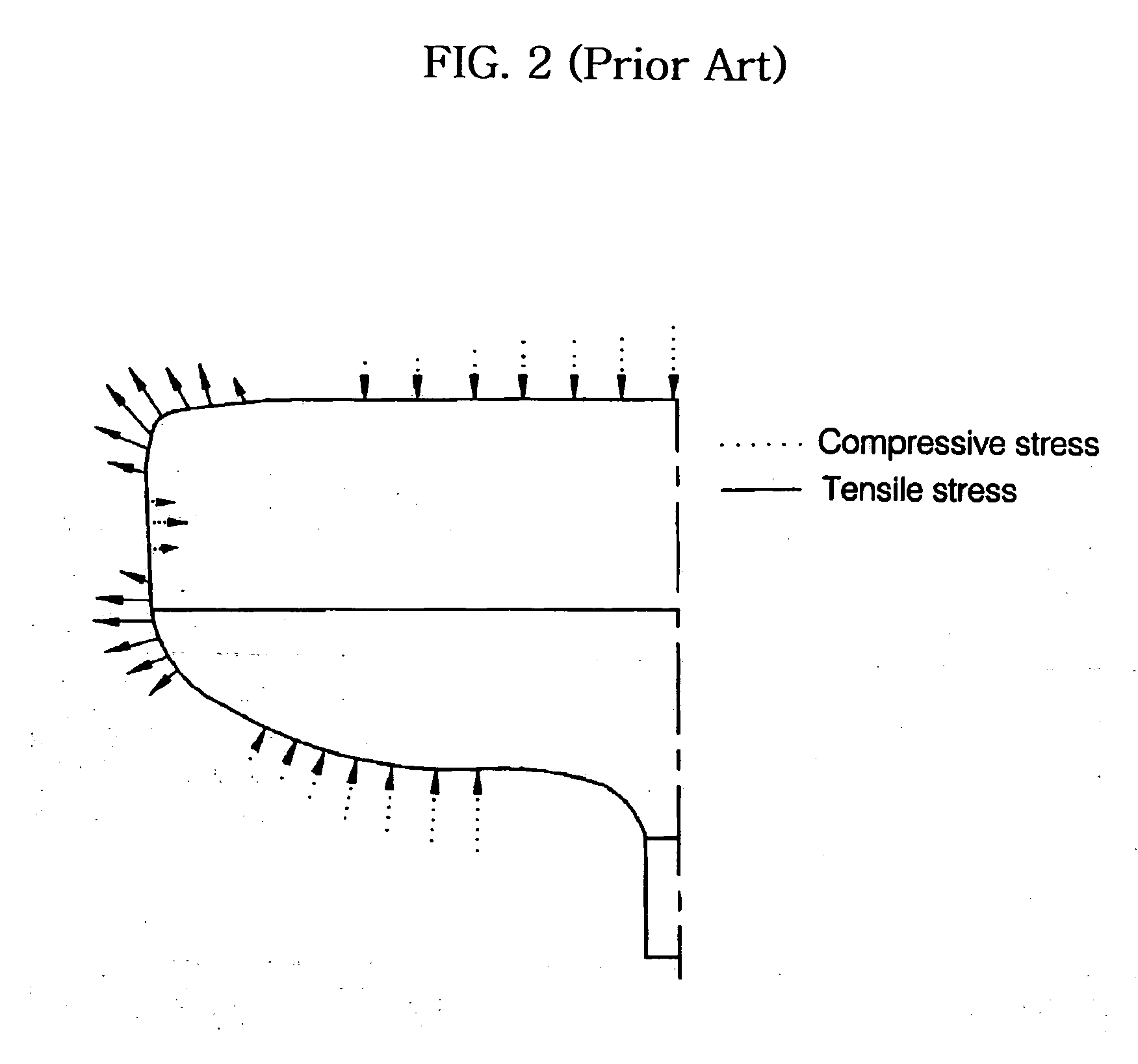
Meanwhile, the cathode ray tube, subjecting to the stresses as stated above, starts to form cracks around a certain region thereof vulnerable to an external shock.
In this case, the tensile stress applied to the surface of the glass envelope accelerates the progress of cracks, causing explosion of the glass envelope if the external shock is excessive.
Furthermore, in the case of the cathode ray tube configured so that a yoke portion of the funnel has a square form in order to allow the deflection yoke to consume only a low amount of electric power, the tensile stress is excessively generated in the glass envelope due to a structural weakness of the funnel, increasing the possibility of breakage in a heat treatment.
Such a physical reinforcing method, however, inevitably generates a high residual tensile stress, in addition to the compressive stress, due to uneven temperature distribution caused during the heat treatment.
This restricts the generation of the compressive stress, causing weight reduction of the glass envelope to be difficult.
The X-rays pass through the front side of the panel of the cathode ray tube, and are harmful to the human body.

Method used


Image

  • Color cathode ray tube
  • Color cathode ray tube
  • Color cathode ray tube

Examples


first embodiment

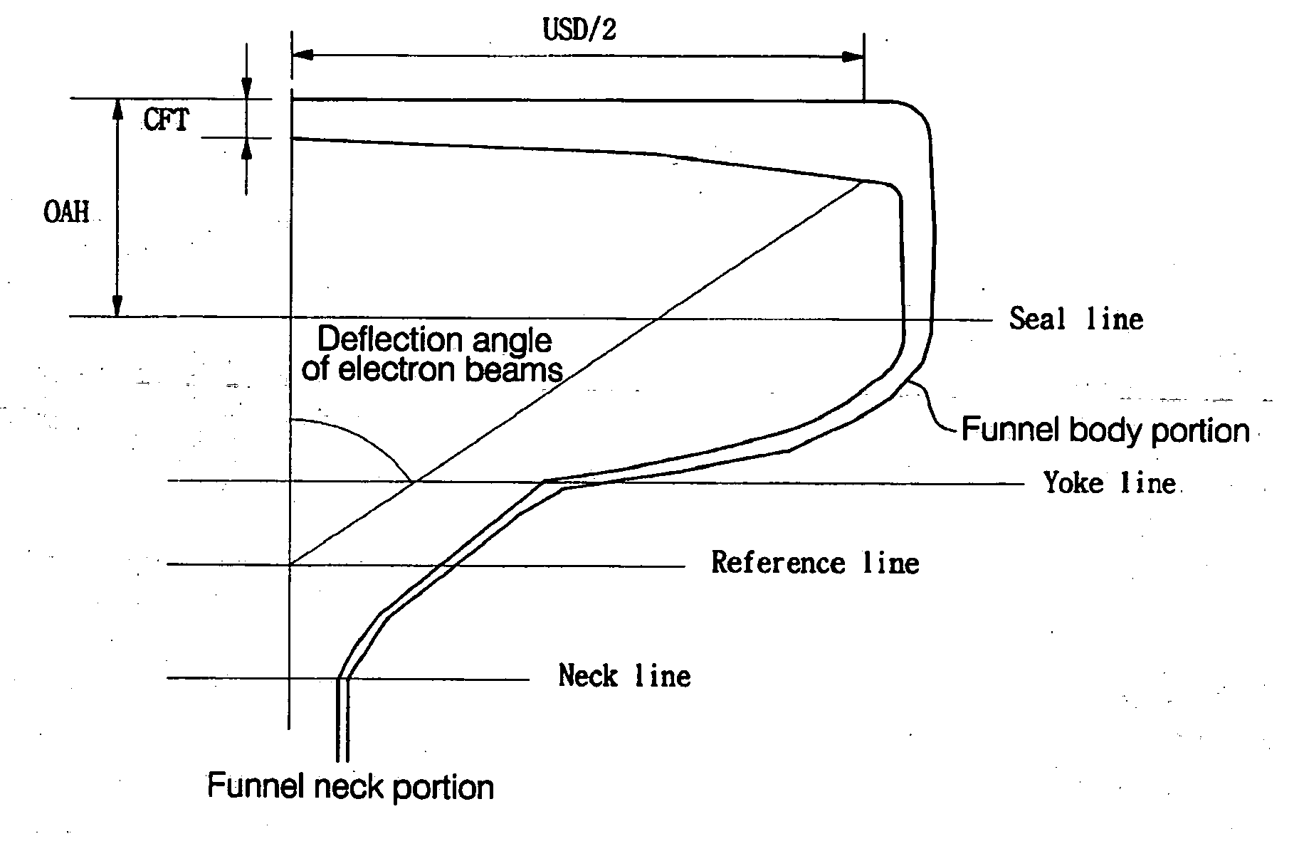
[0028] The following Table 1 represents comparative results between a conventional cathode ray tube and the cathode ray tube of the present invention in view of vacuum stress values. In the present embodiment, the curvature radius Ro of the outer surface of the panel is in a range of 5000 mm to 100000 mm, and other length and thickness of respective regions of the panel are given as follows.

TABLE 1VacuumStressEx.OAHCFTUSDOAH / (OAH * CFT) / TmTm(Mpa)No.(mm)(mm)(mm)USDUSD(%)(%)panelfunnelThe155.98.4406.70.1371.15583.761.85.75.2present248.98.4406.70.1201.01083.761.85.24.8invention3579.5406.70.1401.33182.858.86.05.34509.5406.70.1231.16882.858.85.85.155810.5406.70.1431.49781.956.15.65.165110.5406.70.1251.31781.956.15.14.7The prior16310.5406.70.1551.62781.556.16.55.8art26310.5406.70.1551.62781.556.16.65.7

[0029] As shown in Table 1, comparing the length and thickness of the respective regions of the panel according to the present invention with those of a conventional panel, it will be appr...

second embodiment

[0052] The following Table 3 represents comparative results between a conventional cathode ray tube and the cathode ray tube of the present invention in view of vacuum stress values. In the present embodiment, the curvature radius Ro of the outer surface of the panel is in a range of 5000 mm to 100000 mm, the diagonal length USD of the effective screen of the panel is in a range of 450 mm to 500 mm, and other length and thickness of respective regions of the panel are given as follows.

TABLE 3VacuumStressEx.OAHCFTUSDOAH / (OAH * CFT) / TmTm(Mpa)No.(mm)(mm)(mm)USDUSD(%)(%)panelfunnelThe1658.4457.20.1421.19483.761.86.65.4present2598.4457.20.1291.08483.761.86.35.1invention3649.5457.20.1401.33082.858.86.95.74609.5457.20.1311.24782.858.86.75.556510.5457.20.1421.49381.956.16.45.566110.5457.20.1331.40181.956.16.04.9The prior178.511.0457.20.1731.90181.554.87.25.9art27911.5457.20.1731.98781.554.86.85.6

[0053] As shown in Table 3, comparing the length and thickness of the respective regions of th...


PUM


Abstract

Disclosed herein is a color cathode ray tube which optimizes the structure of a glass panel and funnel to achieve weight reduction thereof. In the color cathode ray tube, a curvature radius of an outer surface of the panel is in a range of 5000 mm to 100000 mm, and the panel is configured to satisfy an expression: 1.0≦(OAH*CFT) / USD≦1.5, where, OAH is a distance from the outer surface of the panel to a sealing surface between the panel and the funnel, USD is a diagonal length of an effective screen of the panel, and CFT is a thickness of a central region of the panel. The cathode ray tube of the present invention has the effects of reducing manufacturing costs through weight reduction thereof, of lowering the degree of breakage during a heat treatment step included in a manufacturing process of the cathode ray tube, resulting in an improved yield, and of effectively intercepting X-rays generated during operation thereof.

Description

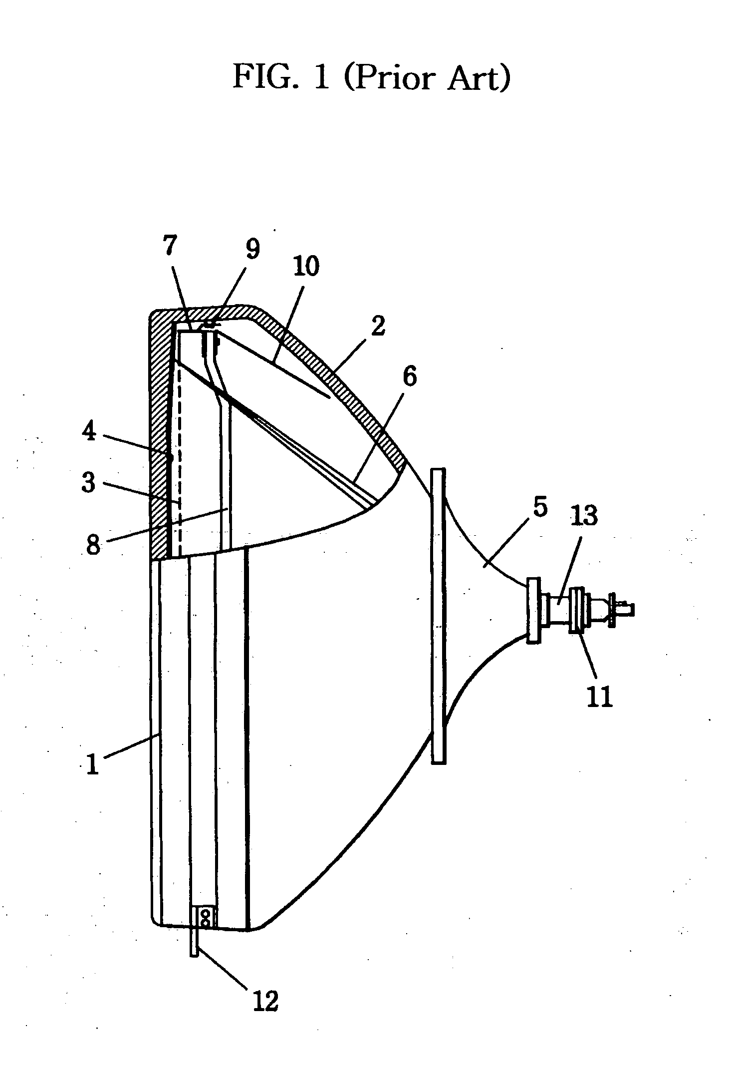
BACKGROUND OF THE INVENTION [0001] 1. Field of the Invention [0002] The present invention relates to a color cathode ray tube having the optimized structure of a panel and funnel. [0003] 2. Description of the Related Art [0004]FIG. 1 is a schematic side view, partially shown in section, illustrating the structure of a conventional color cathode ray tube. As shown in FIG. 1, the conventional color cathode ray tube is basically configured in such a manner that a cone-shaped glass funnel 2 is fused to a rear end of a glass panel 1. The panel 1 has a fluorescent plane 4, which is formed as Red, Green and Blue fluorescent materials are applied to an inner surface of the panel 1, and explosion-proof means is fixed at a front side of the panel 1. Such a color cathode ray tube comprises electron guns inserted in a neck portion 13 of the funnel 2 and adapted to emit electron beams 6, a deflection yoke 5 adapted to deflect the electron beams 6, and a shadow mask 3 mounted at an inner side of ...

Claims


Application Information

Patent Timeline
Patent Type & Authority Applications(United States)
IPC IPC(8): H01J29/02H01J29/86
CPCH01J2229/862H01J29/861H01J29/02
Inventor BAEK, JAE SEUNG
Owner LG PHILIPS DISPLAY KOREA CO LTD
Why Eureka
Try Eureka