Optical navigation based on laser feedback or laser interferometry

a laser feedback and optical navigation technology, applied in the field of optical mouse, can solve problems such as power consumption of ic chips

Inactive Publication Date: 2005-06-23
PIXART IMAGING INC
View PDF6 Cites 32 Cited by
  • Summary
  • Abstract
  • Description
  • Claims
  • Application Information

AI Technical Summary

Problems solved by technology

One drawback of the optical mouse is the power consumed by the IC chip, especially when the optical mouse is cordless and powered by batteries.

Method used


Image

  • Optical navigation based on laser feedback or laser interferometry
  • Optical navigation based on laser feedback or laser interferometry
  • Optical navigation based on laser feedback or laser interferometry

Examples


Embodiment Construction

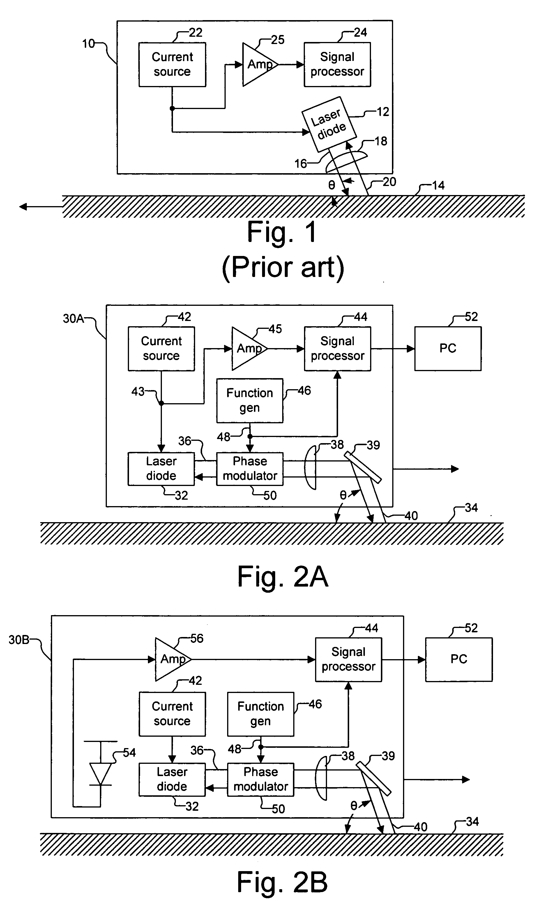
[0009]FIG. 1 illustrates a conventional laser Doppler velocimeter (LDV) 10 that uses the optical self-mixing property of a semiconductor laser diode 12 to detect the velocity of a moving surface 14. Semiconductor laser diode 12 emits light 16 focused by a lens 18 onto moving surface 14. Moving surface 14 scatters a portion of light 16, shown as backscattered light 20, back into the laser cavity at a Doppler shifted frequency. The interference between light 16 inside the laser cavity and backscattered light 20 results in a fluctuation of the light intensity with a beat frequency that is equal to the differences of the two light frequencies. The difference is provided by the following formula: Δ⁢ ⁢v=2⁢v⁢ ⁢cos⁢ ⁢θλ,(1)

where Δν is the frequency difference between light 16 and backscattered light 20, ν is the speed of moving surface 14, θ is the angle of the laser beam direction relative to the velocity of the stationary surface 14, and λ is the wavelength of the laser light.

[0010] Wh...


PUM


Abstract

A computer cursor control device includes (1) a light source generating light directed toward a stationary surface, (2) an optional phase modulator, (3) an optional function generator causing the phase modulator to periodically phase shift the light, and (4) a signal processor determining a direction in which the device is moving from a beat frequency or an asymmetry in the light intensity. Another computer cursor control device includes (1) an optical element combining reference and measurement beams to form a heterodyned beam, (2) a phase modulator located in an optical path of the reference beam or the measurement beam, (3) a function generator causing the phase modulator to phase shift the reference beam, and (4) a signal processor determining a direction in which the device is moving from a beat frequency of the heterodyned beam.

Description

DESCRIPTION OF RELATED ART [0001] A typical optical mouse uses a light-emitting diode (LED) to bounce light off a surface onto a complimentary metal-oxide semiconductor (CMOS) sensor. The CMOS sensor captures images of the surface and sends them to a digital signal processor (DSP) for analysis. The DSP detects pattern changes over a sequence of images to determine how far the mouse has moved and sends the corresponding coordinates to the computer. The CMOS sensor and the DSP are typically implemented in a single integrated circuit (IC) chip. One drawback of the optical mouse is the power consumed by the IC chip, especially when the optical mouse is cordless and powered by batteries. SUMMARY [0002] In one embodiment of the invention, a cursor control device for a computer includes (1) a light source generating light being directed toward a stationary surface, wherein a portion of the light reflects back into the light source and causes an intensity fluctuation of the light, (2) a pha...

Claims


Application Information

Patent Timeline
Patent Type & Authority Applications(United States)
IPC IPC(8): G06F3/033G06F3/042G09G5/00G09G5/08
CPCG06F3/0317G06F3/03545G06F3/03543
Inventor VANWIGGEREN, GREGORY D.BANEY, DOUGLAS M.GORDON, GARY B.
Owner PIXART IMAGING INC
Why Eureka
Try Eureka