Combined light source for projection display

Inactive Publication Date: 2005-06-23
3M INNOVATIVE PROPERTIES CO
View PDF98 Cites 50 Cited by
  • Summary
  • Abstract
  • Description
  • Claims
  • Application Information

AI Technical Summary

Benefits of technology

[0004] In view of the above, there is a need to increase the brightness of the light source used in i

Problems solved by technology

Accordingly, to achieve a desirable color temperature in the image light, a significant p

Method used


Image

  • Combined light source for projection display
  • Combined light source for projection display
  • Combined light source for projection display

Examples


Embodiment Construction

[0023] The present invention is applicable to optical systems and is particularly applicable to projection systems, particularly to projection systems that use liquid crystal image display units.

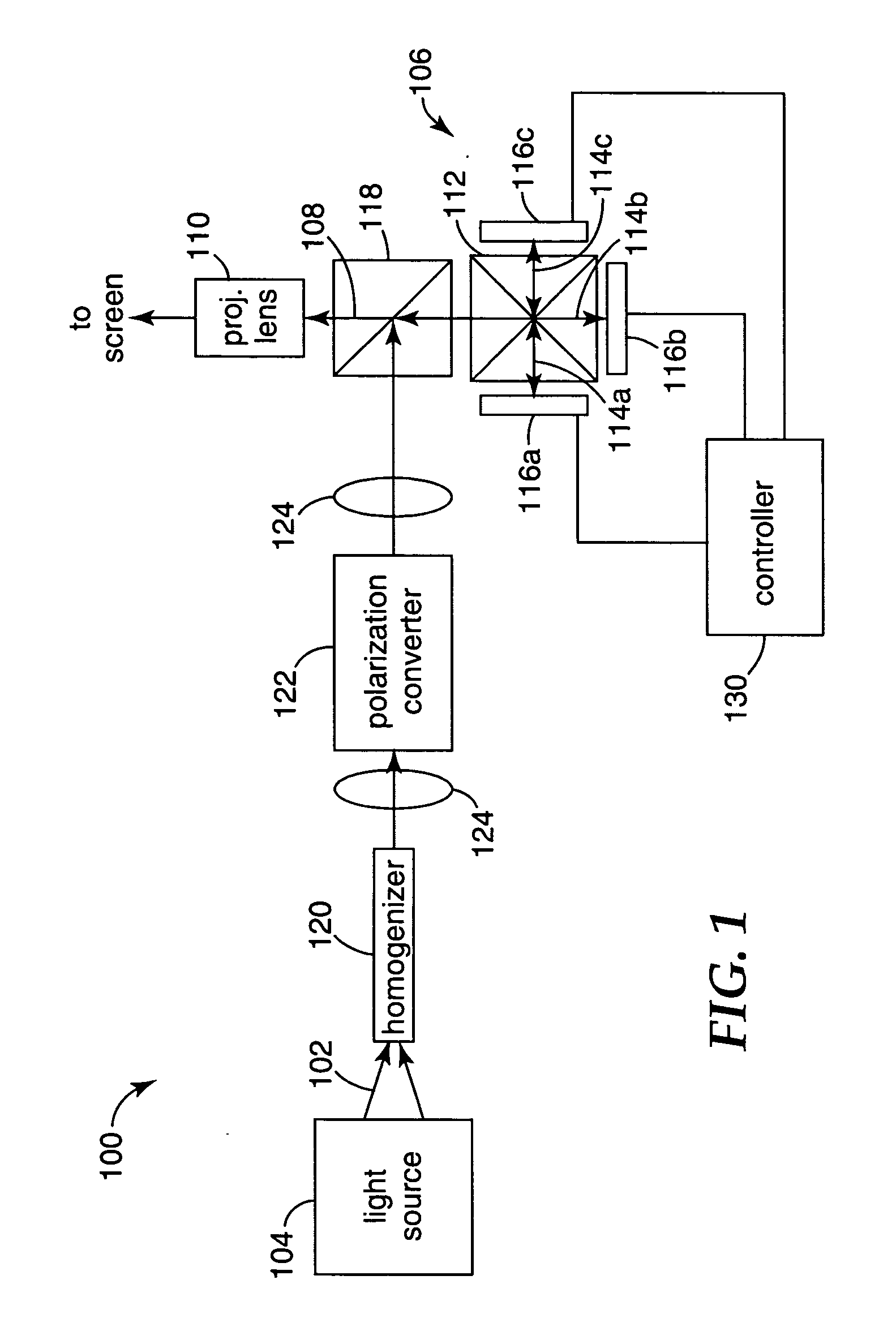
[0024] A schematic illustration of a projection system 100 is presented in FIG. 1. In general terms, light 102 from a light source 104 is directed to an image display device 106. Image light 108 from the image display device 106 then propagates through a projection lens system 110 for projection on a screen. The projection system may be a rear projection system, for example as is commonly found in rear projection televisions, or may be a front projection system, for example as is found in front projection televisions and display systems.

[0025] In the illustrated embodiment, the image display device 106 comprises a color separation / combiner 112 that splits the light 102 into beams of three different primary colors 114a, 114b and 114c, for example red, green and blue, each of which is direct...


PUM


Abstract

High pressure mercury arc lamps are commonly used as the illumination source in many projection systems. Such lamps may be deficient in either output power or spectrum, and so it is desirable to combine the light from the lamp with light from a second light generator. The second light generator may be another mercury lamp or a solid state source, such as one or more light emitting diodes. Different ways of combining light from two light generators are described. The second light source may be an arrangement of a number of red LEDs that supplements the red light produced by the mercury light. A tunnel integrator may be used to homogenize the combined light beam and to reduce the angular separation between the light beams from the two light generators.

Description

FIELD OF THE INVENTION [0001] The invention relates to optical systems, and more particularly to projector systems that use two or more light sources. BACKGROUND [0002] Projection systems, used for projecting an image on to a screen, use several different components for providing efficient illumination of the image display unit. Projection systems typically use a lamp to generate the illumination light, with several optical elements being disposed between the lamp and the image display unit to efficiently transfer the light from the lamp to the image display unit. The image display unit may use different mechanisms for imposing an image on the incident beam of light. For example, the image display unit may use absorption, as with a photographic slide, polarization, as with a liquid crystal display, or by the deflection of light, as with a micromechanical array of individually addressable, tiltable mirrors. Some image display units require that differently colored components of the i...

Claims


Application Information

Patent Timeline
IPC IPC(8): H04N9/31
CPCH04N9/3105H04N9/3197H04N9/3164H04N9/3152H04N5/74
Inventor MAGARILL, SIMONARDASHNIKOV, BORISENGLISH, R. EDWARD JR.
Owner 3M INNOVATIVE PROPERTIES CO
Why Eureka
Try Eureka