Method and apparatus for producing microchannel plate using corrugated mold

a technology of corrugated molds and microchannel plates, which is applied in the manufacture of electrode systems, electric discharge tubes/lamps, electron multiplier details, etc., can solve the problems of high production costs, excessive temperature enhancement, and difficulty in large-area mcps production, and achieve cost reduction

Inactive Publication Date: 2005-06-23
KOREA ADVANCED INST OF SCI & TECH
View PDF12 Cites 4 Cited by
  • Summary
  • Abstract
  • Description
  • Claims
  • Application Information

AI Technical Summary

Benefits of technology

[0013] It is, therefore, an object of the present invention to solve the problems in the prior art and to provide a method for manufacturing a microc...

Problems solved by technology

However, the above method is disadvantageous in terms of high producing costs, and difficulty in the production of large area of MCPs, since the diameter of the glass fiber should be uniformly decreased upon the drawing process and also, excessive enhancement of the temperatures occurs at a central portion of the bundled glass fibers upon the combining process.
However, this method is disadvantageous in terms of high producing costs, since it requires a very accurate coating process of the secondary emitter onto the inside of the microchannel 40-100 times longer than the diameter of the previo...

Method used


Image

  • Method and apparatus for producing microchannel plate using corrugated mold
  • Method and apparatus for producing microchannel plate using corrugated mold
  • Method and apparatus for producing microchannel plate using corrugated mold

Examples


example 1

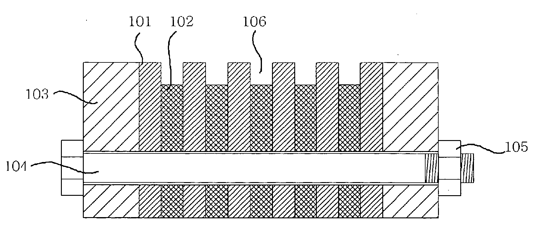
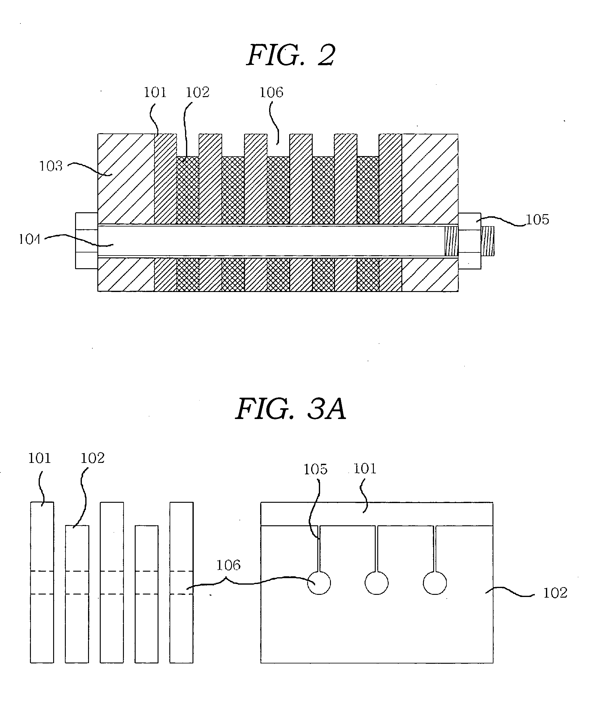
[0035] As shown in FIG. 4a, a first substrate 111 was placed on a corrugated mold, prepared by use of a plurality of first thin plates 101 and a plurality of second thin plates 102. As the first substrate 111, a polymer substrate formed of engineering plastics or a glass substrate was used. As shown in FIG. 4b, the first substrate 111 was heated by use of a heater 112 and a fan 113 until it was pliable enough to be vacuumed. While a vacuum was applied from a plurality of valleys 106 of the corrugated mold beneath the first substrate 111, assisted by an air passage in the mold, a high pressure air was applied over the first substrate 111. After a cooling process, a first corrugated substrate 111a having corrugated top and bottom surfaces resulted, to which a predetermined air pressure was applied through the air passage of the corrugated mold, to release the first corrugated substrate 111a from the corrugated mold.

[0036] Then, as shown in FIG. 4c, a secondary emitter was coated onto...

example 2

[0040] As shown in FIG. 5a, a substrate 111 was placed on a corrugated mold and a flat substrate 121 was placed on the substrate 111. As the substrate 111, a polymer substrate formed of engineering plastics or a glass substrate was used. As shown in FIG. 5b, the substrate 111 was heated by use of a heater 112 and a fan 113. Then, while a vacuum was applied from the valleys 106 of the corrugated mold beneath the substrate 111, assisted by the air passage in the mold, a pneumatic or hydraulic pressure was applied over the flat substrate 121. Thereby, the heated substrate 111 was drawn down into the valleys 106 of the corrugated mold. After a cooling process, a corrugated substrate 111b having a corrugated bottom surface resulted, to which a predetermined air pressure was applied through the air passage, to release the corrugated substrate 111b from the corrugated mold.

[0041] As shown in FIG. 5c, a secondary emitter was coated onto the corrugated substrate 111b, to prepare a secondary...

example 3

[0044] Instead of controlling electric resistance of the secondary emitter-coated layer 115 as in Example 1, an electroconductive layer 131 was positioned below the secondary emitter-coated layer 115, thereby feeding electrons to the secondary emitter-coated layer 115. Therefore, as shown in FIG. 6a, a first corrugated substrate 111a and a second flat substrate 114 prepared in the same manner as in Example 1 were coated with an electroconductive material to prepare the electroconductive layer 131. Then, a secondary emitter was coated on the electroconductive layer 131, thereby giving a secondary emitter-coated layer 115.

[0045] As such, as the electroconductive material, use was taken of conductive materials, such as metals or ITO (indium tin oxide). In addition, as the secondary emitter, SiO2, MgO, Al2O3, ZnO, CaO, SrO, LaO3, MgF2, CaF2, or LiF was used.

[0046] As shown in FIG. 6b, a plurality of the first corrugated substrates 111a and a plurality of the second flat substrates 114...


PUM


Abstract

Disclosed is a method and apparatus for producing a microchannel plate (MCP) using a corrugated mold, characterized in that each of corrugated substrates formed by the corrugated mold is coated with a secondary emitter and then layered, thereby easily producing a large area of the MCP and decreasing production costs of the MCP. The MCP producing method includes placing a first flat substrate on the corrugated mold, vacuum forming the first flat substrate so that both surfaces thereof are corrugated, coating a secondary emitter onto both surfaces of each of the first corrugated substrate and a second flat substrate, and alternately layering a plurality of the first corrugated substrates and a plurality of the second substrates each coated with the secondary emitter, to form microchannels.

Description

PRIORITY CLAIM [0001] This application claims priority from Korean Patent Application No. 10-2002-0080954 filed 18 Dec. 2002, which is herein incorporated by reference. FIELD OF THE INVENTION [0002] The present invention pertains, in general, to a method and apparatus for producing a microchannel plate (MCP) using a corrugated mold. More specifically, the present invention is directed to an MCP producing mold apparatus having a corrugated shape, and a method of producing an MCP using the MCP producing mold apparatus by coating a secondary emitter onto a corrugated substrate and layering a plurality of the corrugated substrates, advantageous in terms of low producing costs and simple producing process. BACKGROUND OF THE INVENTION [0003] MCPs are used as a plate-shaped electronic component formed by vertically stacking a plurality of microchannels each functioning to multiply incident electrons. Thus, the MCPs have been mainly employed for electronic devices requiring electron multipl...

Claims


Application Information

Patent Timeline
IPC IPC(8): B05D3/00B05D5/12H01J1/30H01J9/00H01J9/12H01J43/24
CPCH01J43/246H01J9/125H01J1/30
Inventor LEE, DAI GILKIM, PO JINLEE, HAK GU
Owner KOREA ADVANCED INST OF SCI & TECH
Why Eureka
Try Eureka