Optimized correction of wafer thermal deformations in a lithographic process

a lithographic process and thermal deformation technology, applied in the field of lithographic equipment, can solve problems such as overlay errors, compromising the quality of exposed patterns, and contributing to overlay errors,

Inactive Publication Date: 2005-06-23
ASML NETHERLANDS BV
View PDF2 Cites 51 Cited by
  • Summary
  • Abstract
  • Description
  • Claims
  • Application Information

AI Technical Summary

Benefits of technology

[0022] Although specific reference may be made in this text to the use of the apparatus according to the invention in the manufacture of ICs, it should be explicitly understood that such an apparatus has many other possible applications. For example, it may be employed in the manufacture of integrated optical systems, guidance and detection patterns for magnet...

Problems solved by technology

There are, however, numerous activities during the lithographic fabrication process that contribute to overlay errors and compromise the quality of the exposed patterns.
Indeed, the very lithographic exposure process used to project the pattern onto the individual target fields C may contribute to overlay errors.
Such defor...

Method used


Image

  • Optimized correction of wafer thermal deformations in a lithographic process
  • Optimized correction of wafer thermal deformations in a lithographic process
  • Optimized correction of wafer thermal deformations in a lithographic process

Examples


first embodiment

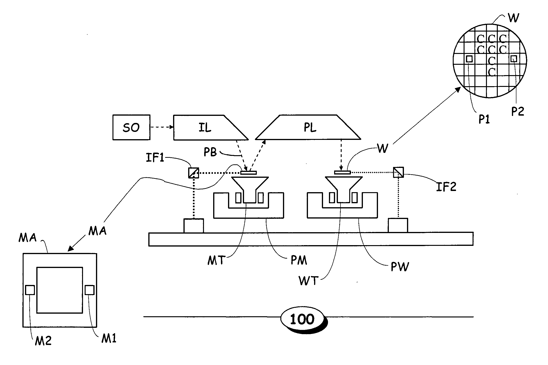
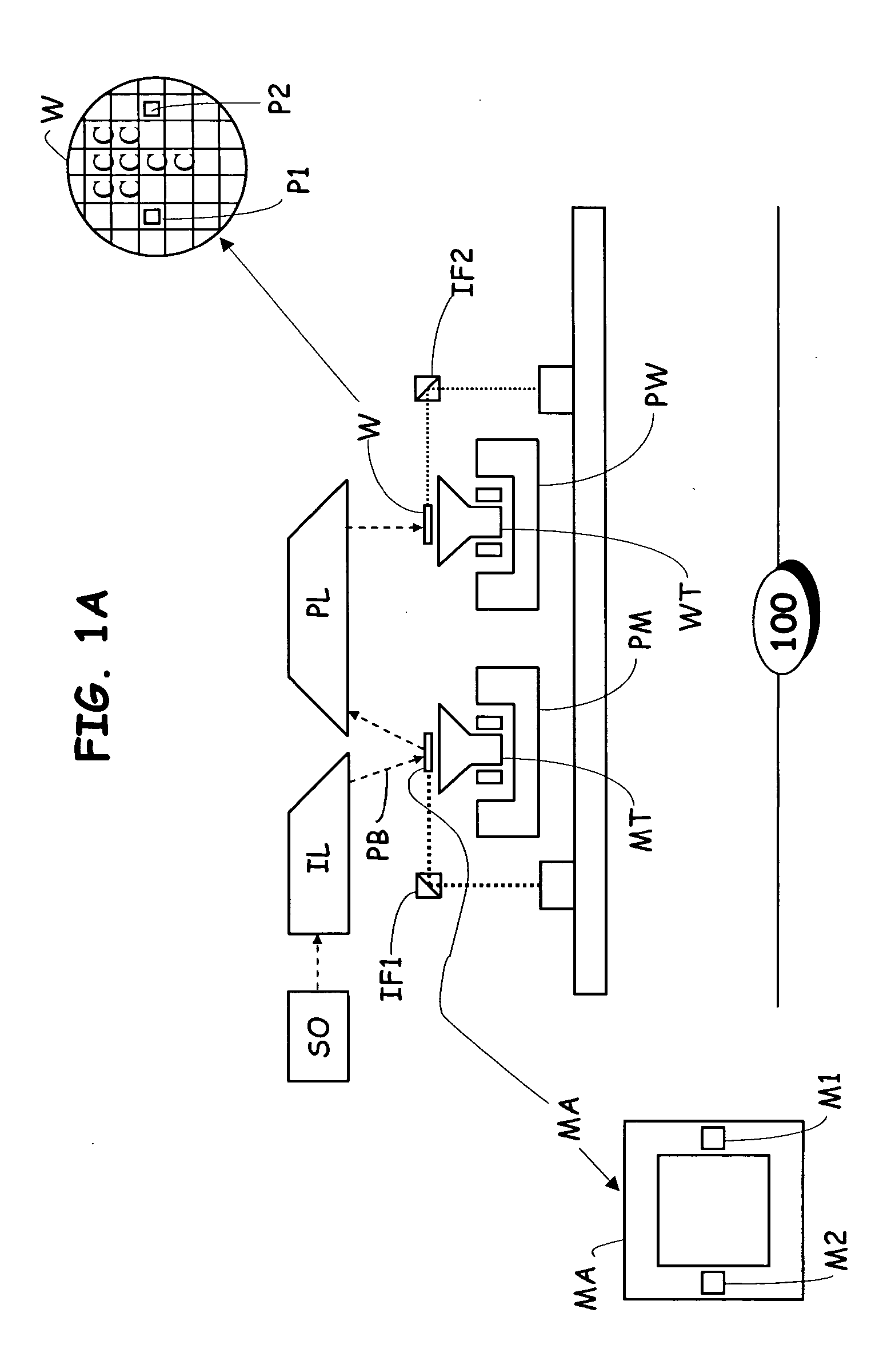
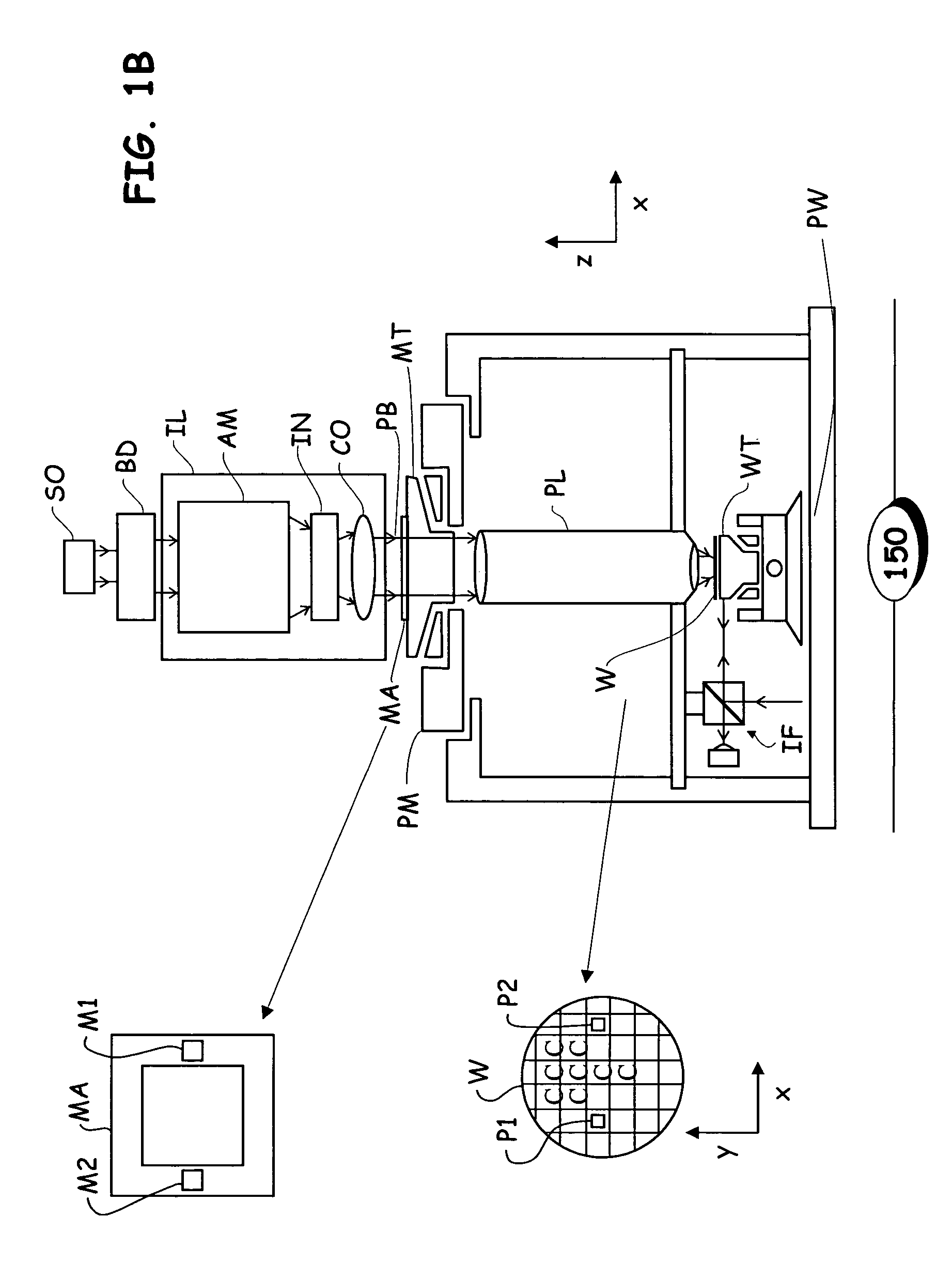
[0065]FIG. 2A schematically depicts the general inventive concept of thermal correction process 200, constructed and operative in accordance with a particular embodiment of the present invention. As indicated in FIG. 2A, correction process 200 commences with procedure task P202, which provides the initial exposure recipe. The exposure recipe designates the amount of energy to be focused by the projection beam PB onto each of the target fields Ci-CN of the wafer substrate W to comply with the manufacturer's specified features and profile of the exposed pattern. It will be appreciated that, for some embodiments, it is desirable to maintain the total energy dose received by the target fields Ci-CN of the wafer substrate W constant. However, even in these embodiments, the exposure time (i.e., scanning speed) and exposure energy (e.g., laser power) may be configured as adjustable parameters in the exposure recipe, provided that the total energy dose remains constant, in order to reduce t...

second embodiment

[0075]FIG. 2B schematically depicts the general inventive concept of thermal correction process 250, constructed and operative in accordance with a particular embodiment of the present invention. As indicated in FIG. 2B, correction process 250 commences with procedure task P252, which provides the initial exposure recipe. As discussed above, the exposure recipe may include exposure time, exposure energy, exposure coordinate positioning, and exposure sequencing information.

[0076] Thermal correction process 250 then advances to procedure task P254, where the target fields Ci-CN of wafer substrate W are successively exposed with the desired pattern by lithographic apparatus 100, 150, in a manner consistent with the description above and in accordance with the exposure recipe.

[0077] After exposure, correction process 250 then progresses to procedure task P256, where the exposed wafer substrate W is subjected to a measurement process. The measurement process is configured to measure va...

third embodiment

[0081]FIG. 3 schematically depicts the general inventive concept of thermal correction process 300, constructed and operative in accordance with a particular embodiment of the present invention. As indicated in FIG. 3, correction process 300 commences with procedure task P302, which provides the initial exposure recipe. As discussed above with respect to the other disclosed embodiments, the exposure recipe may include exposure time, exposure energy, exposure coordinate positioning, and exposure sequencing information.

[0082] Thermal correction process 300 then advances to procedure task P304, where thermal corrections are determined. In this embodiment, the thermal corrective information takes the form of predictive deformation information based on a global expansion model. In particular, as depicted in FIG. 1G, for example, the deformation due to thermal effects of a selected point (x,y) within the area of each target field Ci may be modeled as: (x+Δx, y+Δy), where Δx, Δy represent...


PUM


Abstract

A method and apparatus of correcting thermally-induced field deformations of a lithographically exposed substrate, is presented herein. In one embodiment, the method includes exposing a pattern onto a plurality of fields of a substrate in accordance with pre-specified exposure information and measuring attributes of the fields to assess deformation of the fields induced by thermal effects of the exposing process. The method further includes determining corrective information based on the measured attributes, and adjusting the pre-specified exposure information, based on the corrective information, to compensate for the thermally-induced field deformations. Other embodiments include the use of predictive models to predict thermally-induced effects on the fields and thermographic imaging to determine temperature variations across a substrate.

Description

BACKGROUND OF THE INVENTION [0001] 1. Field of the Invention [0002] The present invention relates to lithographic apparatus and, more particularly, to correcting wafer substrate deformations in a lithographic apparatus. [0003] 2. Description of the Related Art [0004] A lithographic apparatus is a machine that applies a desired pattern onto a target portion or target field of a substrate. Lithographic apparatus can be used, for example, in the manufacture of integrated circuits (ICs). In that circumstance, a patterning device, such as a mask (i.e., reticle), may be used to generate a circuit pattern corresponding to an individual layer of the IC, and this pattern can be imaged onto a target field (e.g. comprising part of, one or several dies) on a substrate (e.g. a silicon wafer) that has a layer of radiation-sensitive material (resist). [0005] In general, a single substrate will contain a network of adjacent target portions or fields that are successively exposed. Known lithographic...

Claims


Application Information

Patent Timeline
IPC IPC(8): G03F7/20H01L21/027G03F9/00
CPCG03F7/70616G03F7/70875G03F7/70783G03F7/70558
Inventor OTTENS, JOOST JEROENVAN DER SCHOOT, HARMEN KLAASSTARREVELD, JEROEN PIETERPETRUS MARIA MAAS, WOUTERUS JOHANNESVENEMA, WILLEM JURRIANUSMENCHTCHIKOV, BORIS
Owner ASML NETHERLANDS BV
Why Eureka
Try Eureka