
Cell culture device

Inactive Publication Date: 2005-06-23
THE AUTOMATION PARTNERSHIP CAMBRIDGE
View PDF4 Cites 5 Cited by
  • Summary
  • Abstract
  • Description
  • Claims
  • Application Information

AI Technical Summary

Benefits of technology

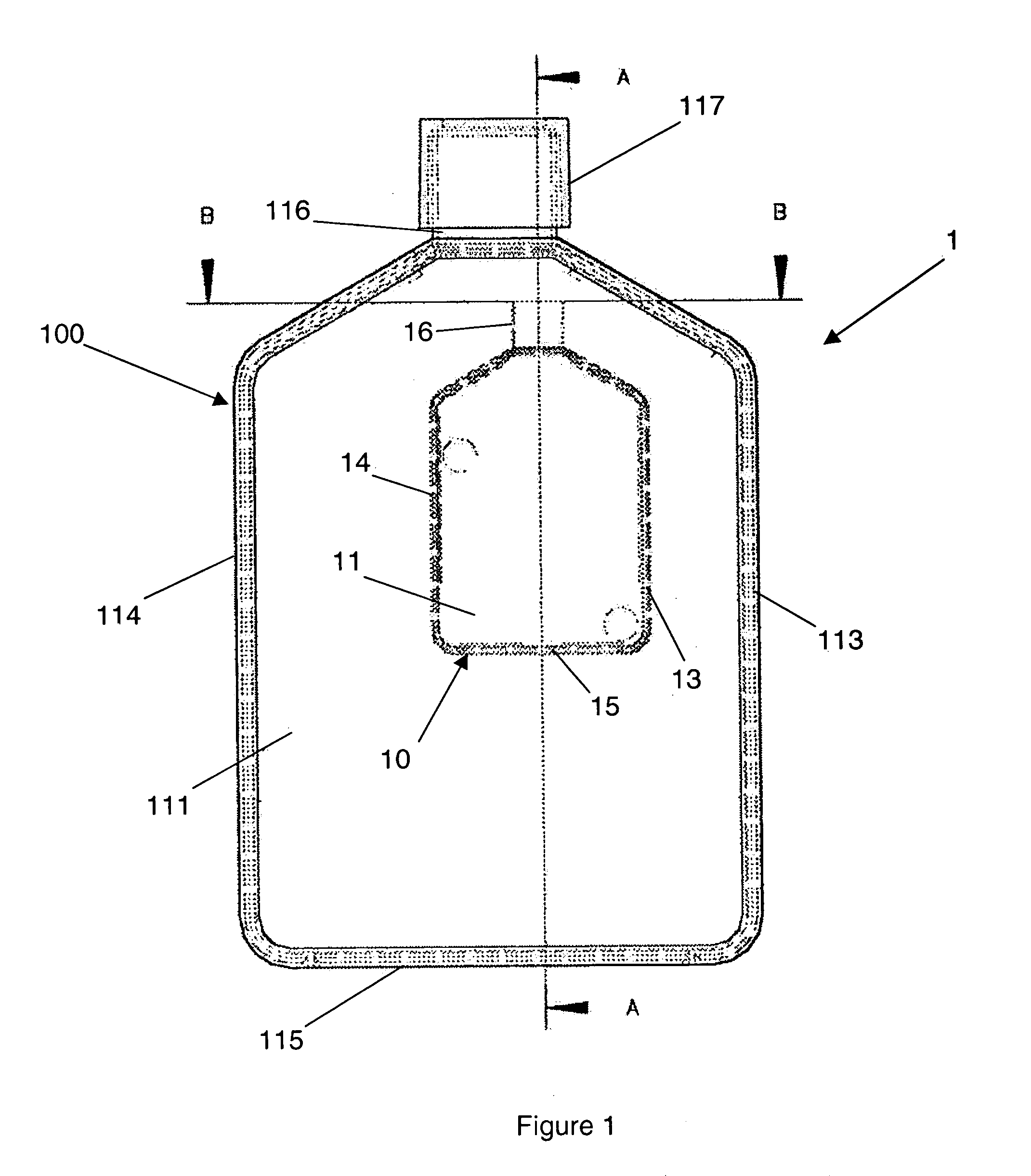
[0009] Preferably the flask is held within the envelope defined by the structure which may comprise a cuboid framework. This enables the structure to interface fully with the storage position within the automated storage system. This provides a greater level of security for the contents of the flask as the movement of the culture device within the storage device is reduced.
[0011] Alternatively, the larger flask may be empty so that, once the cell culture has reached its maximum population density within the small flask the contents may be transferred in to the larger flask using, for example, a pipette and culturing may continue within the larger flask. This allows any form of identification that has been applied to the flask to remain valid whilst the medium is cultured in firstly the smaller and latterly the larger flask.

Problems solved by technology

However, it can be difficult to begin a cell culture in a standard T-flask as the concentrations may be too low as a result of the large surface area available.
However, the problem arises as to how to store and transport these new smaller flasks as they do not fit conveniently in to pre-existing storage and incubation systems as these are configured to deal with standard flasks that have previously been developed by the industry, all of which are larger than the new generation of small flasks.
However, the storage and incubation systems into which these flasks are usually placed are frequently large and complex devices that cannot easily or cheaply be replaced.

Method used


Image

  • Cell culture device
  • Cell culture device
  • Cell culture device

Examples


Embodiment Construction

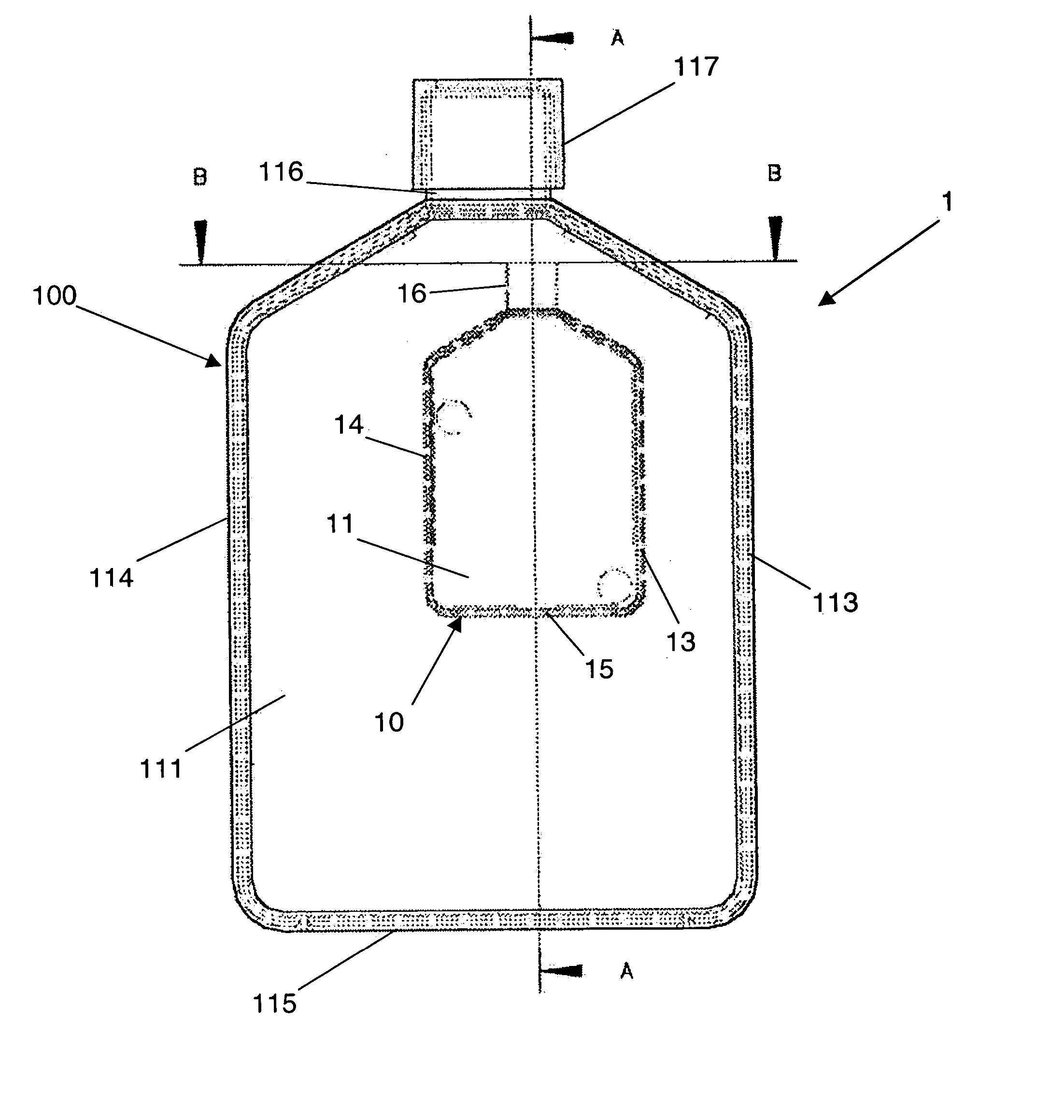
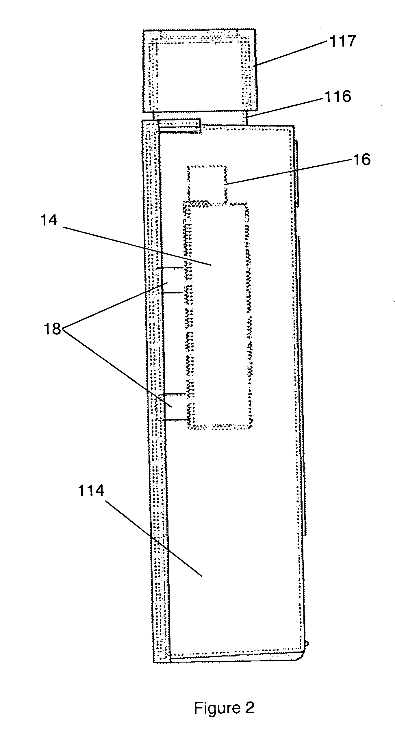
[0025]FIG. 1 shows a first example of a cell culture device 1 according to the present invention. Within the internal volume of the culture device 1 there is provided a smaller flask 10 in which cells may be cultured. The flask 10 consists of are four orthogonal walls 11, 12, 13 and 14 and a base 15. There are two major walls 13 and 14 and two minor walls 11 and 12. Above the four orthogonal walls 11 to 14 the walls of the flask 10 converge to meet at a neck portion 16. The narrowing of the flask 10 at the neck portion 16 ensures that the contents of the flask 10 remain within the flask 10. The neck 16 could screw threaded and may co-operate, in use, with a cap 17 to seal the contents of the flask from the ambient atmosphere and also from the contents of the cell culture device 1. The use of a cap 17 to close the smaller flask 10 is only appropriate in some applications as a result of potential contamination of the sample held within the flask 10. In order to overcome this problem a...


PUM


Abstract

A cell culture device 1 comprises a flask 10 within which, in use, cells are cultured. The flask 10 is connected to a structure 100 that is constructed to enable the flask 10 to be held, in use, within a recess of a cell culture system. The volume of the envelope defined by the structure 100 and the flask 10 is greater than the volume of the flask 10.

Description

BACKGROUND [0001] The present invention relates to a cell culture device. [0002] It is common, within the field of cell biology, to culture cells in order to harvest biologically active compounds produced by the cells, or indeed the cells themselves. Such cells are generally cultured on static plates which are enclosed in a bottle or flask. Flasks may generally be accessed through a neck portion, closed by means of a cap. When the flask is in use it is laid on its side so that the maximum possible surface area is horizontal. The cell cultivating medium covers the inner surface of this flask wall. Over time, the industry has developed a number of sizes of flask that are considered to be standard. One of these, known as the T-flask has four orthogonal walls (two major walls and two minor walls) and is configured so that the maximum surface area is available to the cells when the flask is laid on one of its major sides. These flasks are then stored in large automated storage systems co...

Claims


Application Information

Patent Timeline
IPC IPC(8): B01L3/08C12M1/24C12M3/00
CPCB01L3/08B01L2300/0609C12M23/48C12M23/34C12M23/08
Inventor MALINGE, DAVID S.
Owner THE AUTOMATION PARTNERSHIP CAMBRIDGE
Learn More