Advanced anisotropic ceramic matrix composite system

Inactive Publication Date: 2005-06-23
GENERAL ELECTRIC CO
View PDF16 Cites 13 Cited by
  • Summary
  • Abstract
  • Description
  • Claims
  • Application Information

AI Technical Summary

Benefits of technology

[0011] One advantage of the matrix composite system of the present invention is that it provides components having substantially uniform thickness which have enhanced mechanical performance in cross ply strength and in shear.
[0012] Another advantage of the matrix composite system of the present invention is that it provides CMC components having substantially uniform thickness irrespective the aspect ratio of the component.
[0013] An additional advantage of the matrix

Problems solved by technology

This combination of desired propertie

Method used


Image

  • Advanced anisotropic ceramic matrix composite system
  • Advanced anisotropic ceramic matrix composite system

Examples


Embodiment Construction

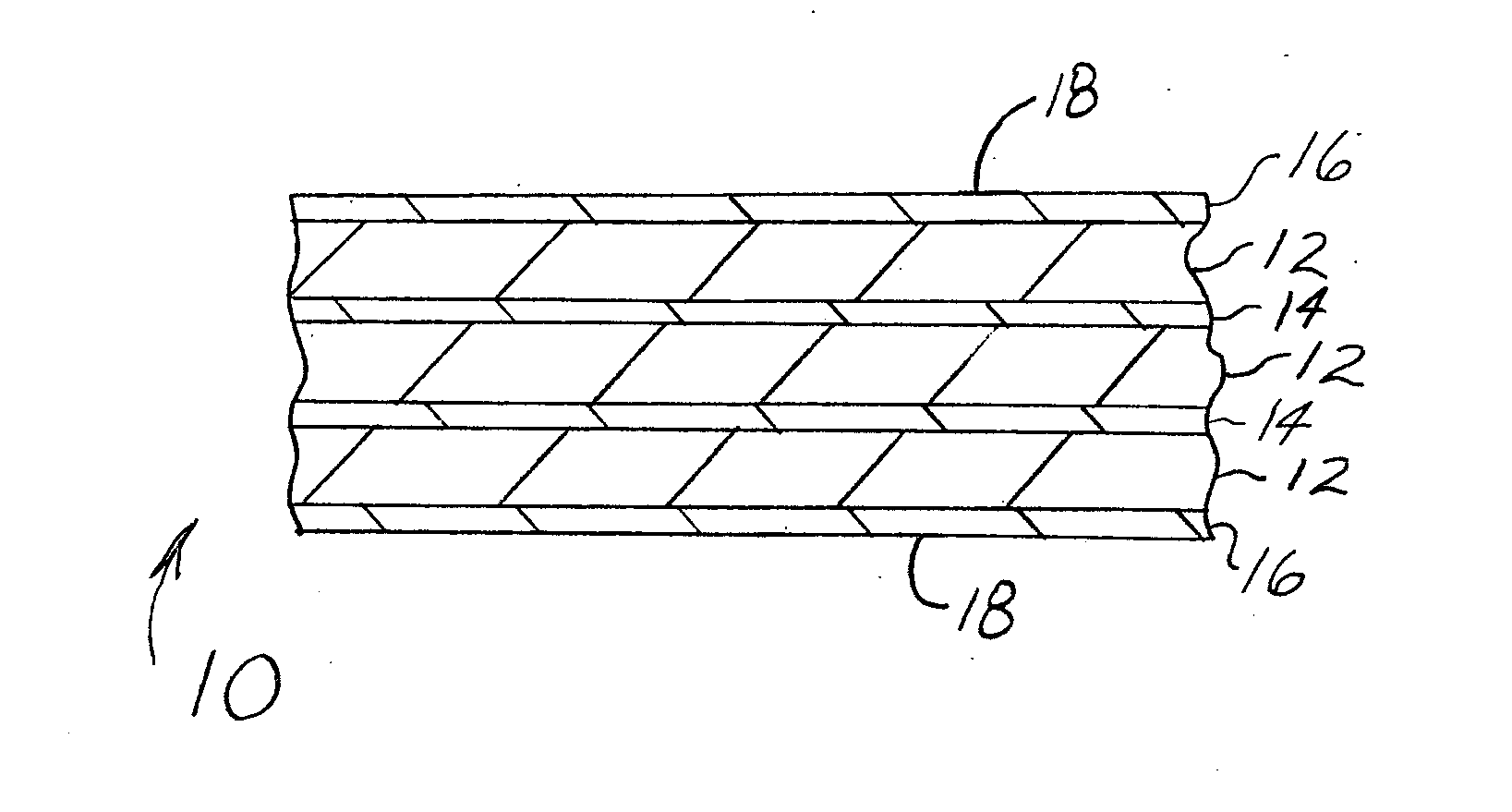
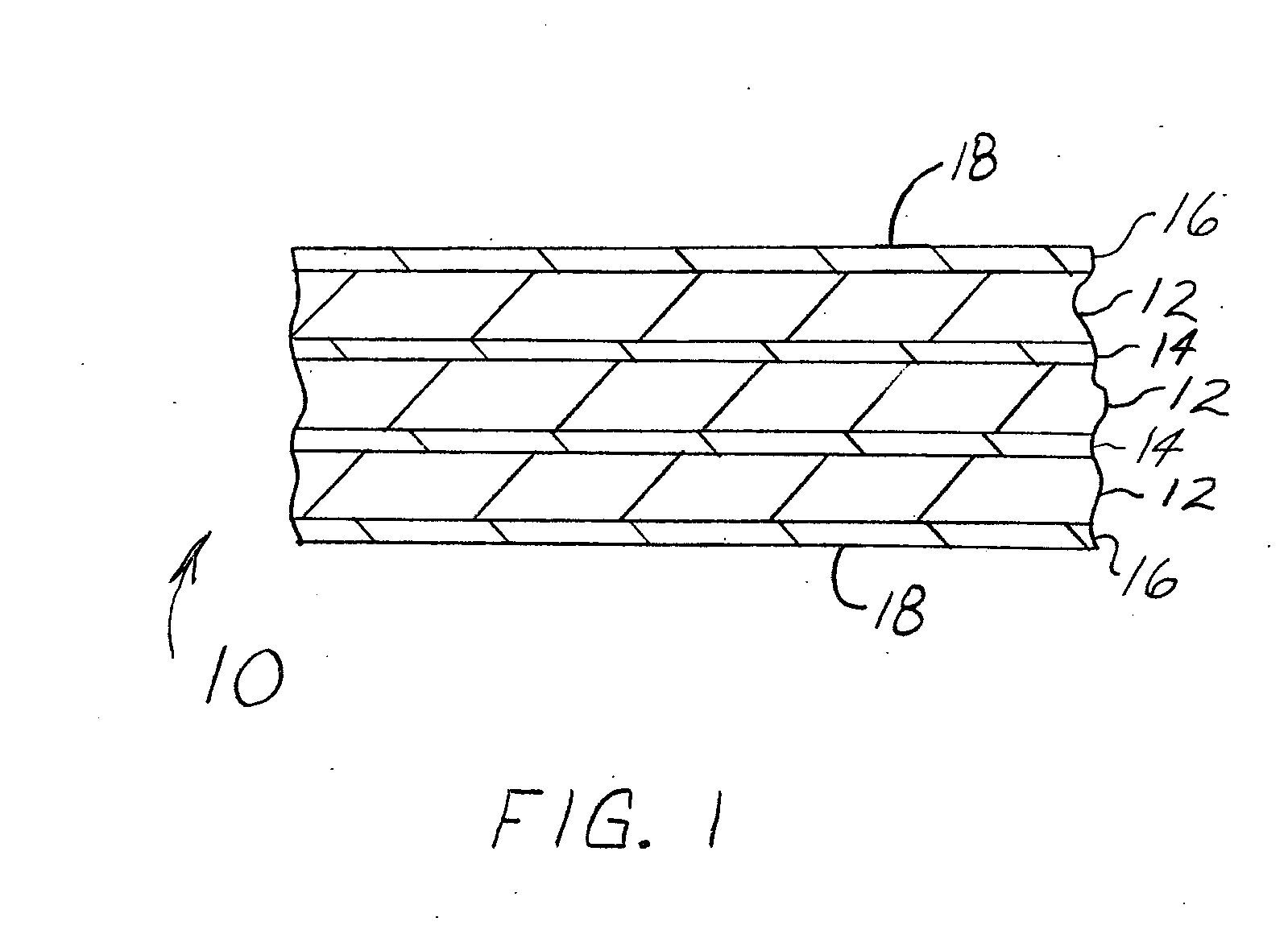
[0017] The present invention is generally applicable to CMC components that operate within environments characterized by relatively high temperatures, and are therefore subjected to a hostile oxidizing environment and severe thermal stresses and thermal cycling. Notable examples of such components include the high and low pressure turbine nozzles and blades, shrouds, combustor liners and augmentor hardware of gas turbine engines. While the advantages of this invention may be described with reference to gas turbine engine hardware, the teachings of the invention are generally applicable to any ceramic or polymeric matrix composite component that may be constructed of stacked fiber cloth plies impregnated with matrix material.

[0018] Represented in FIG. 1 is a matrix composite system 10 in accordance with this invention. In a preferred embodiment, the matrix composite system 10 is shown as including a plurality of ceramic prepreg layers 12 having intervening layers 14 inserted between...


PUM

PropertyMeasurementUnit
Thicknessaaaaaaaaaa
Thicknessaaaaaaaaaa
Thicknessaaaaaaaaaa

Abstract

A ceramic matrix composite system includes multiple stacked layers of ceramic fiber cloth impregnated with resin matrix material. The resin matrix material in each of the fiber cloth layers substantially remains with the same layer during subsequent processing. Ceramic-containing material inner layers are applied between each of the fiber cloth layers enhancing the cross ply strength of the composite system.

Description

BACKGROUND OF THE INVENTION [0001] The present invention relates generally to a ceramic matrix composite system. Specifically, the present invention relates to a ceramic matrix composite system for high temperature service and method for producing the ceramic matrix composite system. [0002] In some applications, a structural part is exposed to high surface temperatures on a heated surface of the part such as in turbine engines used in aircraft. These structural part constructions, such as ceramic matrix composites (CMCs), provide structural support for components associated with engine exhaust, and possibly the engine itself [0003] Typically, CMCs are composed of multiple woven fiber fabric material layers impregnated with an amount of matrix material, often referred to as a prepreg. The fabric layers are arranged to define a desired shape and then subjected to an elevated temperature under slight pressure typically applied by a vacuum bag, typically referred to as debulking, to bon...

Claims


Application Information

Patent Timeline
IPC IPC(8): B32B18/00B32B27/04B32B27/12
CPCB32B18/00B32B2315/02C04B2235/3217C04B2235/3418C04B2235/36C04B2235/5436C04B2237/704C04B2235/77C04B2237/341C04B2237/343C04B2237/348C04B2237/38C04B2235/5445Y10T442/3683Y10T442/2041Y10T442/3496Y10T442/3472Y10T442/2975Y10T442/2123Y10T442/2148
Inventor IVKOVICH, DANIEL PETER JR.SKOOG, ANDREW JAYMURPHY, JANE ANNRENTZ, THOMAS WALTER
Owner GENERAL ELECTRIC CO
Why Eureka
Try Eureka