Multi-stage fuel deoxygenator

a fuel deoxygenator and multi-stage technology, applied in the direction of machines/engines, combustion air/fuel air treatment, combustion gas purification/modification, etc., can solve the problem of unoptimized size of a fuel deoxygenator or oxygen scavenger module capable of removing the proportion of dissolved air removed by the combination, and achieve the effect of increasing the usable cooling capacity of fuel

Inactive Publication Date: 2005-06-23
UNITED TECH CORP
View PDF22 Cites 19 Cited by
  • Summary
  • Abstract
  • Description
  • Claims
  • Application Information

AI Technical Summary

Benefits of technology

[0013] Accordingly, the fuel delivery system of this invention provides for the removal of increased amounts of dissolved

Problems solved by technology

The size of a fuel deoxygenator or oxygen scavenger module capable of removi

Method used


Image

  • Multi-stage fuel deoxygenator
  • Multi-stage fuel deoxygenator
  • Multi-stage fuel deoxygenator

Examples


Embodiment Construction

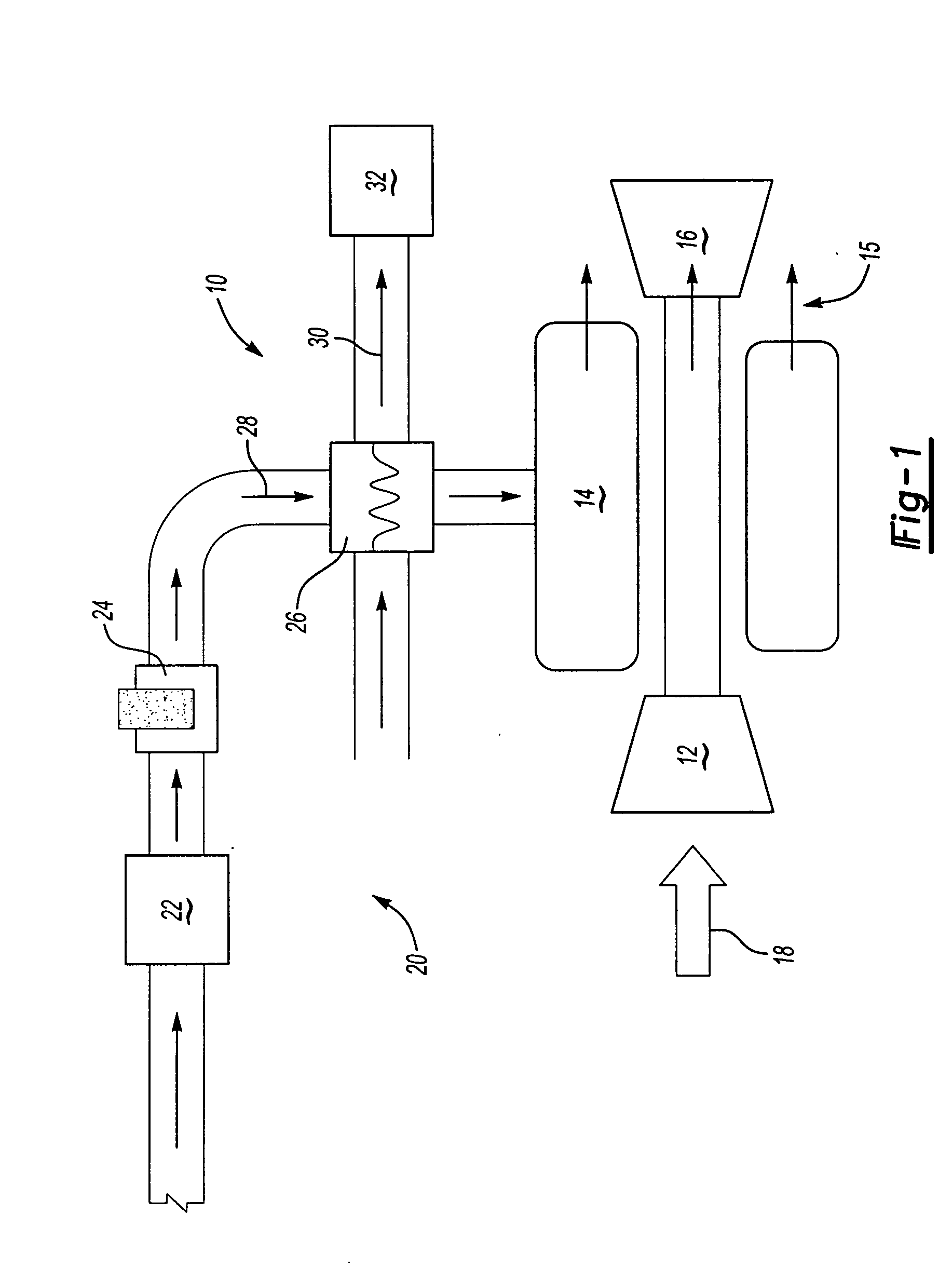
[0021] Referring to FIG. 1, a gas turbine engine assembly 10 includes a compressor 12, a combustor 14 and a turbine 16. Airflow 18 entering the compressor 12 is compressed to a high pressure and directed towards the combustor 14. In the combustor 14, fuel is mixed with the high-pressure air and ignited. Resulting hot combustion gases 15 exhausted from the engine 10 drive the turbine 16. Fuel is delivered to the combustor 14 through a fuel delivery system 20. Although a gas turbine engine 10 is shown, other energy conversion assemblies known to a worker skilled in the art would benefit from application of this invention. The fuel delivery system 20 of this invention includes a fuel deoxygenator 22 and an oxygen scavenger module 24.

[0022] The fuel system 20 also includes a heat exchanger 26 for rejecting heat from other systems, schematically shown at 32 to fuel 28. The other system can include cooling of cooling air or other fluids circulated through the engine 10. The specific cool...


PUM

PropertyMeasurementUnit
Partial pressureaaaaaaaaaa
Flow rateaaaaaaaaaa
Sizeaaaaaaaaaa

Abstract

A fuel delivery system for an energy conversion device includes a fuel deoxygenator and an oxygen scavenger module for removing dissolved oxygen and increasing the usable cooling capability of a fuel. Fuel emerging from the fuel-deoxygenating device flows into the oxygen-scavenging module where a second portion, smaller than the first portion of oxygen is removed from the fuel. The combination of the oxygen scavenger and the fuel deoxygenator provides an increase in removal of dissolved oxygen relative to the use of either device alone. The combination provides the desired increase in deoxygenation of fuel without the corresponding increase in device size.

Description

BACKGROUND OF THE INVENTION [0001] This invention generally relates to a fuel delivery system for an energy conversion device, and specifically to a fuel delivery system including a fuel deoxygenator and an oxygen scavenger module for removing dissolved oxygen to increase the usable cooling capability of a fuel. [0002] A gas turbine engine is an energy conversion device typically used in aircraft and in power generation applications. A gas turbine engine typically includes a compressor, a combustor and a turbine. Air entering the compressor is compressed and directed toward a combustor. Fuel is combined with the high-pressure air and ignited. Combustion gases produced in the combustor drive the turbine. [0003] It is common practice to use fuel as a cooling medium for various systems onboard an aircraft. The usable cooling capacity of a particular fuel is limited by the formation of insoluble products referred to as “coke”. The formation of coke deposits is dependent on the amount of...

Claims


Application Information

Patent Timeline
IPC IPC(8): B01D19/00F02M27/02B01D61/00B01D69/10B01D69/12B01D71/36B01J20/26C10K1/00F02C3/24F02C7/22F02C7/224
CPCB01D19/0031B01D19/0068B01D19/0073B01D61/00Y02T50/672B01D63/082F02C7/22F02C7/224B01D63/06F23K2900/05082Y02T50/60B01D19/00C10K1/00B01D63/0822
Inventor CORDATOS, HARRYSPADACCINI, LOUIS J.VANDERSPURT, THOMAS H.
Owner UNITED TECH CORP
Why Eureka
Try Eureka