Transformerless power conversion in an inverter for a photovoltaic system

a technology of transformerless power conversion and photovoltaic system, which is applied in the direction of pv power plants, semiconductor devices, transportation and packaging, etc., can solve the problems of reducing the efficiency of the power conversion process, significant energy loss, and the cost of a photovoltaic system, and achieves the effect of small filter components and less expensiv

Inactive Publication Date: 2005-06-30
GENERAL ELECTRIC CO
View PDF11 Cites 129 Cited by
  • Summary
  • Abstract
  • Description
  • Claims
  • Application Information

AI Technical Summary

Benefits of technology

[0008] Thus, it would be desirable to combine modules of the above-described transformerless inverter topologies to meet such requirements for higher power applications. It w

Problems solved by technology

This requirement may present a problem when interfacing, for example, with a 120/240 Vac utility grid that also requires its neutral point to be grounded.
The need of such a

Method used


Image

  • Transformerless power conversion in an inverter for a photovoltaic system
  • Transformerless power conversion in an inverter for a photovoltaic system
  • Transformerless power conversion in an inverter for a photovoltaic system

Examples


Embodiment Construction

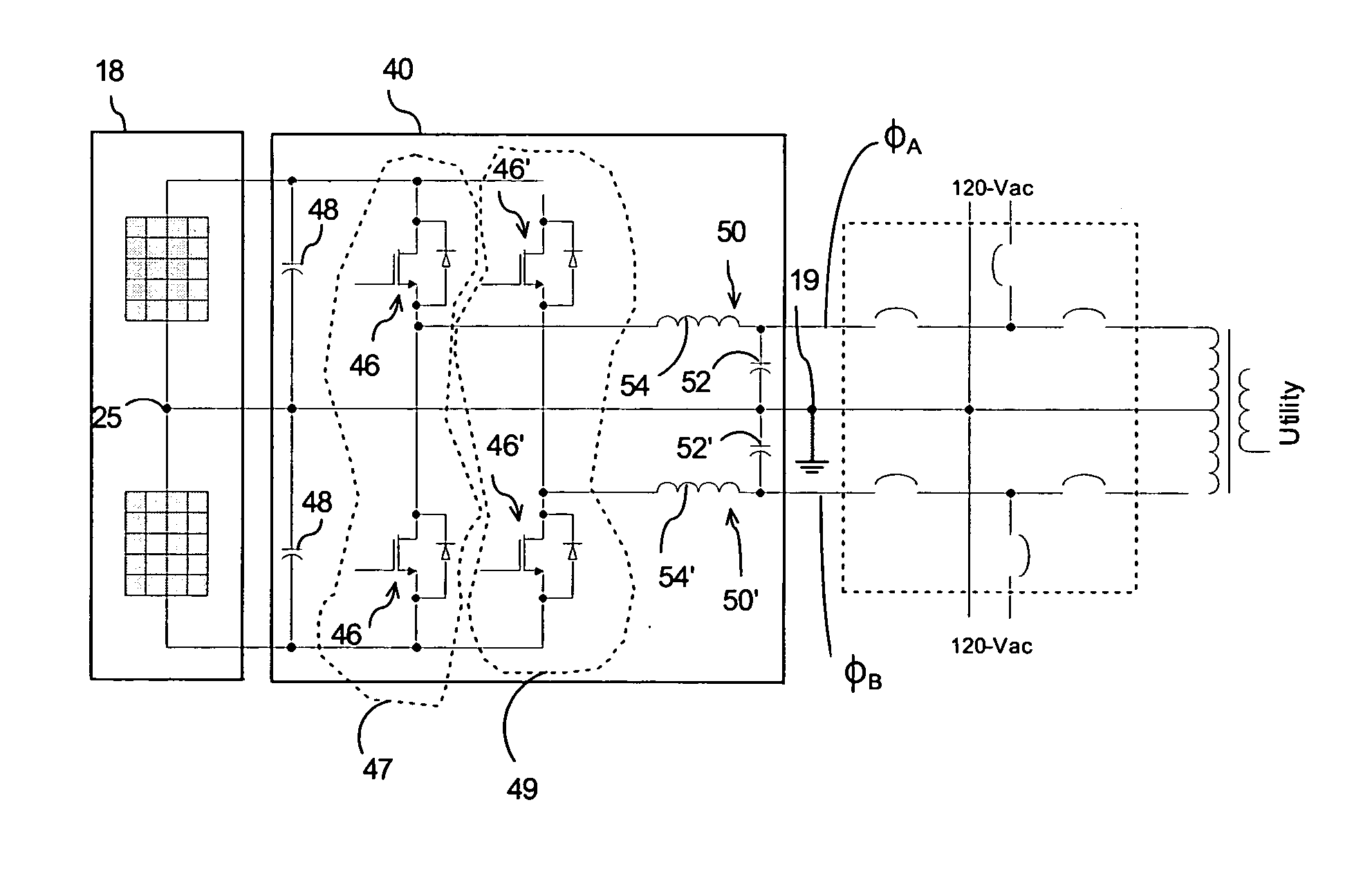
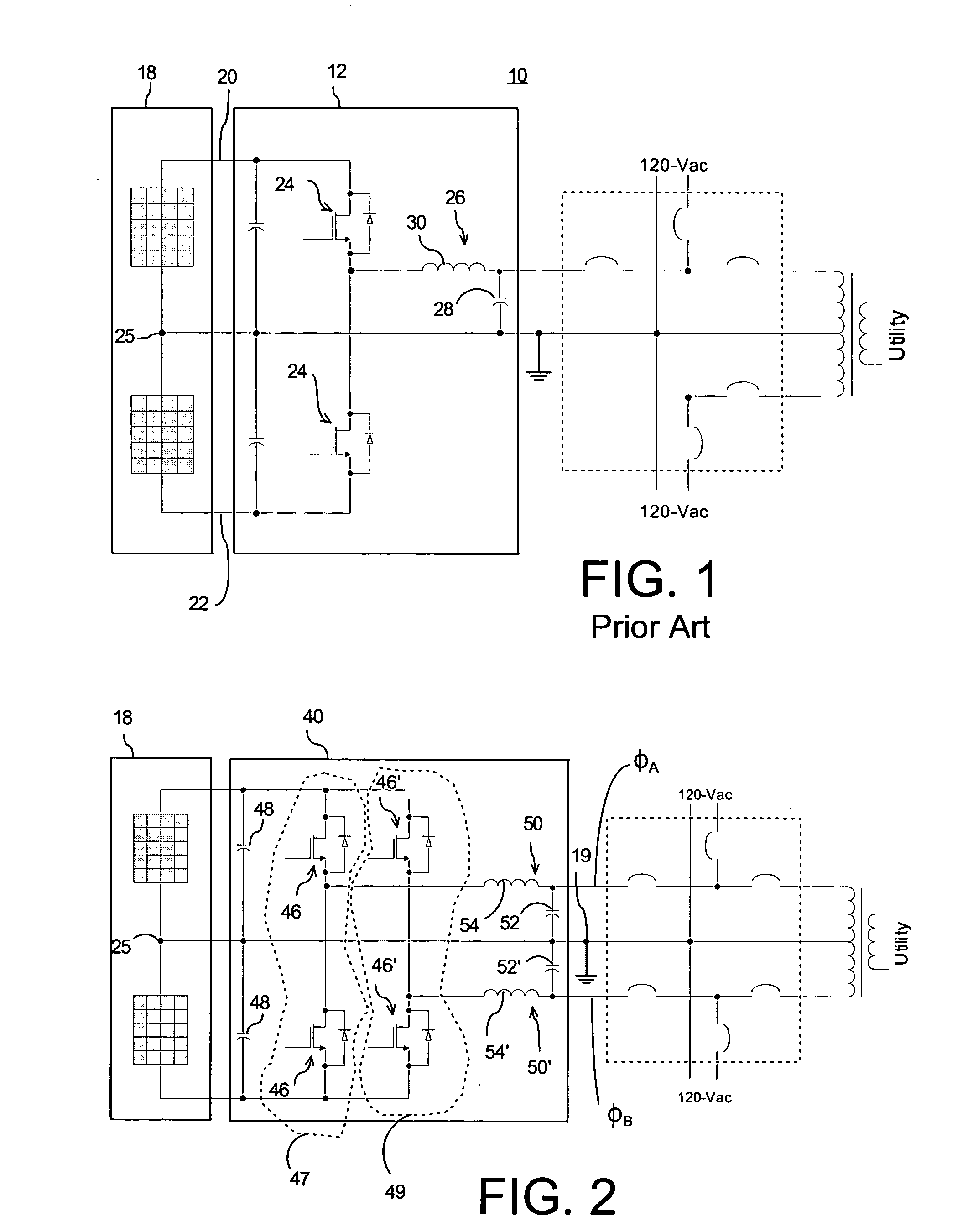
[0017] The fact that the half bridge topology illustrated in FIG. 1 supplies power just to one side of the 120-Vac line may be acceptable for relatively low power applications, such as less than approximately 2.5 kW. However, for relatively higher power applications (such as may range from about 3 kW to about 5 kW), it may be desirable to supply power to both sides of the ac ground, such as sides ØA and ØB in FIG. 2. For example, it may be desirable to supply power to a 120-Vac grid on both sides of neutral. This can be accomplished by employing an inverter 40 comprising a full bridge topology, such as may be obtained by coupling two half bridge inverters (one on each side of neutral) as shown in FIG. 2. In this embodiment, it can be seen that power can be injected in a balanced manner into both sides of neutral while maintaining both the bipolar photovoltaic array 18 and the grid neutral point at ground potential. That is, the array and the utility grid are both grounded at a commo...


PUM


Abstract

A transformerless photovoltaic system that may benefit from inverter topologies more suitable for ripple current cancellation techniques is provided. In one exemplary embodiment, the system may combine basic modules of straightforward inverter topologies to meet requirements for higher power applications and may comprise a bipolar photovoltaic array, and a full-bridge inverter electrically coupled to the bipolar photovoltaic array. The full bridge inverter may comprise first and second inverter legs that may be arranged to energize two phases of a grid electrically coupled to the photovoltaic system. In one exemplary embodiment, switching signals applied to switching devices in each of the first and second inverter legs may be adjusted relative to one other to reduce ripple current therein, thereby reducing the size of components used by the system.

Description

[0001] This invention was made with U.S. Government support through Government Contract Number 55792 awarded by the Department of Energy, and, in accordance with the terms set forth in said contract, the U.S. Government may have certain rights in the invention.BACKGROUND OF THE INVENTION [0002] Electrical codes (such as the National Electrical Code—NEC) that may be applicable to photovoltaic systems in some cases may require that one side of a photovoltaic array be grounded. See for example, NEC Article 690. This requirement may present a problem when interfacing, for example, with a 120 / 240 Vac utility grid that also requires its neutral point to be grounded. In order to ground both the array and the utility as required by code, photovoltaic systems have commonly employed an isolation transformer. [0003] In the case of a typical 60-Hz or 50-Hz power conversion application, the isolation transformer may usually comprise a device of substantial bulk and weight placed between the grid...

Claims


Application Information

Patent Timeline
IPC IPC(8): H01L31/00H02J3/38H02J7/35
CPCH02J7/35H02J3/383Y02E10/566Y02E10/563H02J2300/24H02J3/381Y02E10/56
Inventor STEIGERWALD, ROBERTROOIJ, MICHAEL DE
Owner GENERAL ELECTRIC CO
Why Eureka
Try Eureka