
Drawing apparatus and method, computer program product, and drawing display system

a technology of drawing apparatus which is applied in the field of drawing apparatus and method, computer program product, and drawing display system, can solve the problems of high power consumption, ineffective utilization of drawing performance, and increased product weight of preparing a plurality of drawing apparatuses,

Inactive Publication Date: 2005-06-30
PIONEER CORP
View PDF11 Cites 18 Cited by
  • Summary
  • Abstract
  • Description
  • Claims
  • Application Information

AI Technical Summary

Benefits of technology

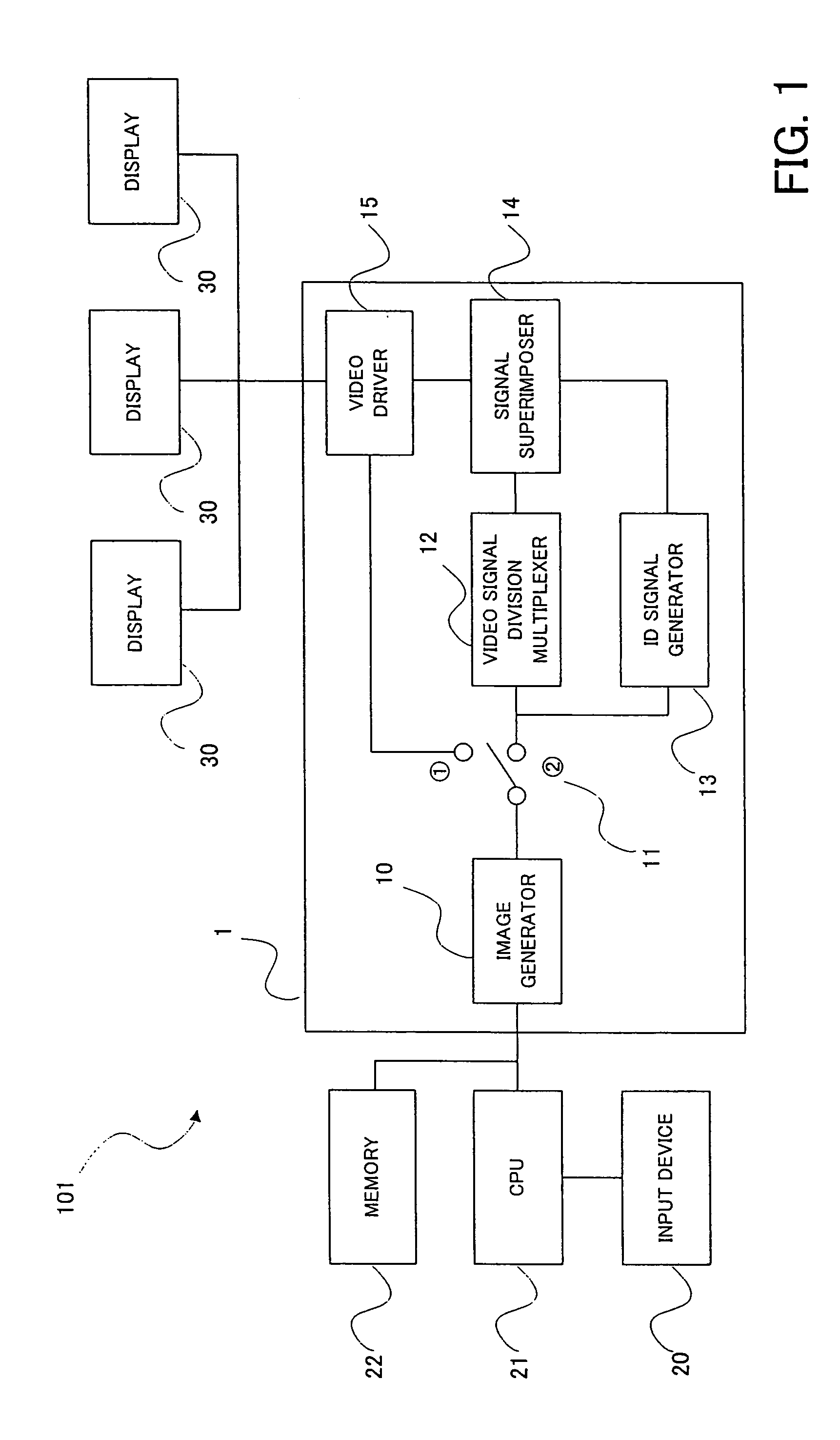
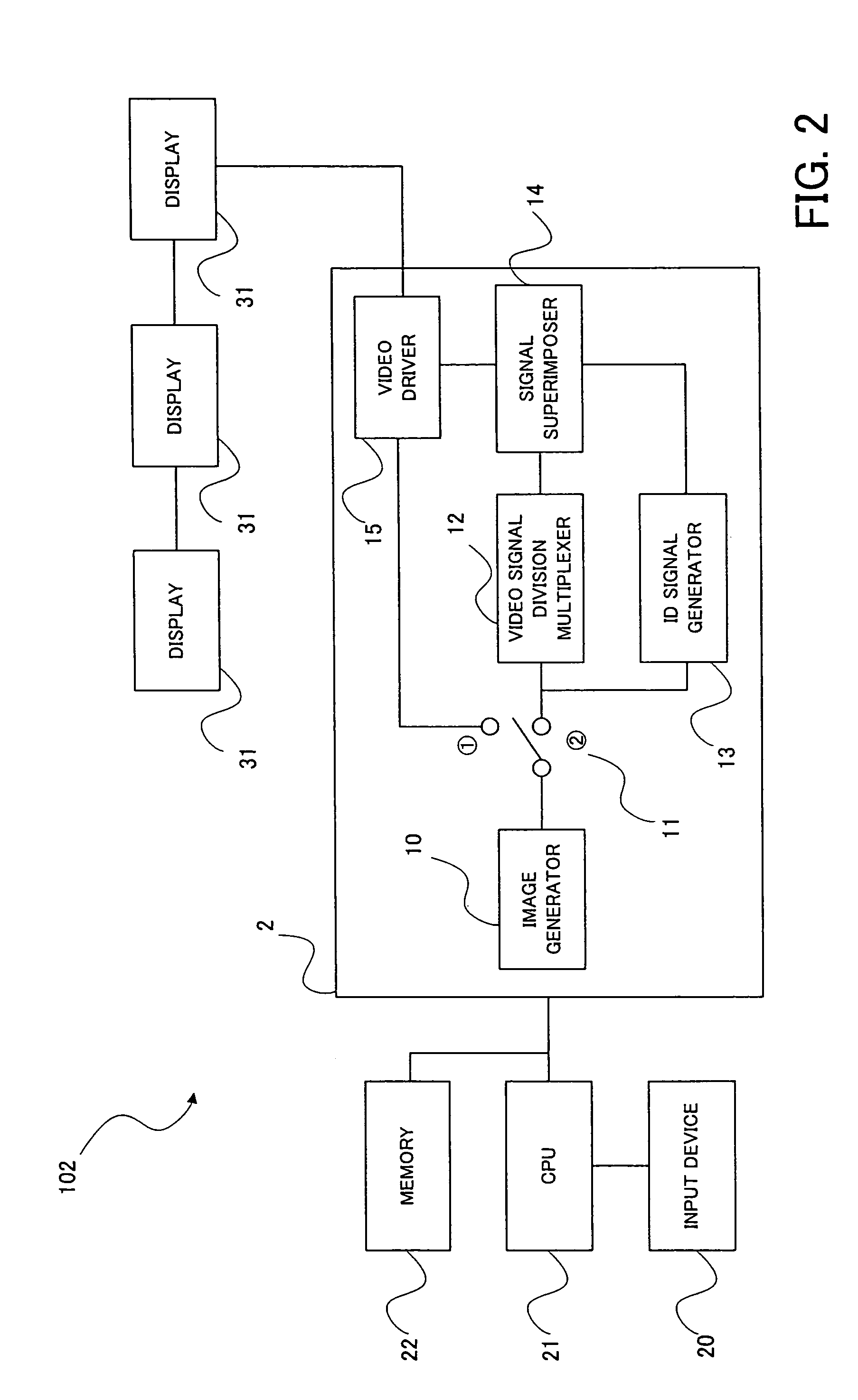
[0011] Consequently, according to this embodiment, since different video signals can be displayed on a plurality of display devices by a single drawing apparatus, the drawing function is fully utilized, the circuit area, parts count and signal transmission path length is reduced, and thereby the product cost and the product weight are reduced. Additionally, there are advantages in that, comparing to the construction with a plurality of drawing apparatuses, the processings are facilitated, and the power consumption is reduced. Therefore, the drawing apparatus allowing an extremely low cost and an efficient operation, and furthermore paying attention to the earth environment from a viewpoint of energy efficiency is presented, while different video images are displayed on a plurality of display devices.
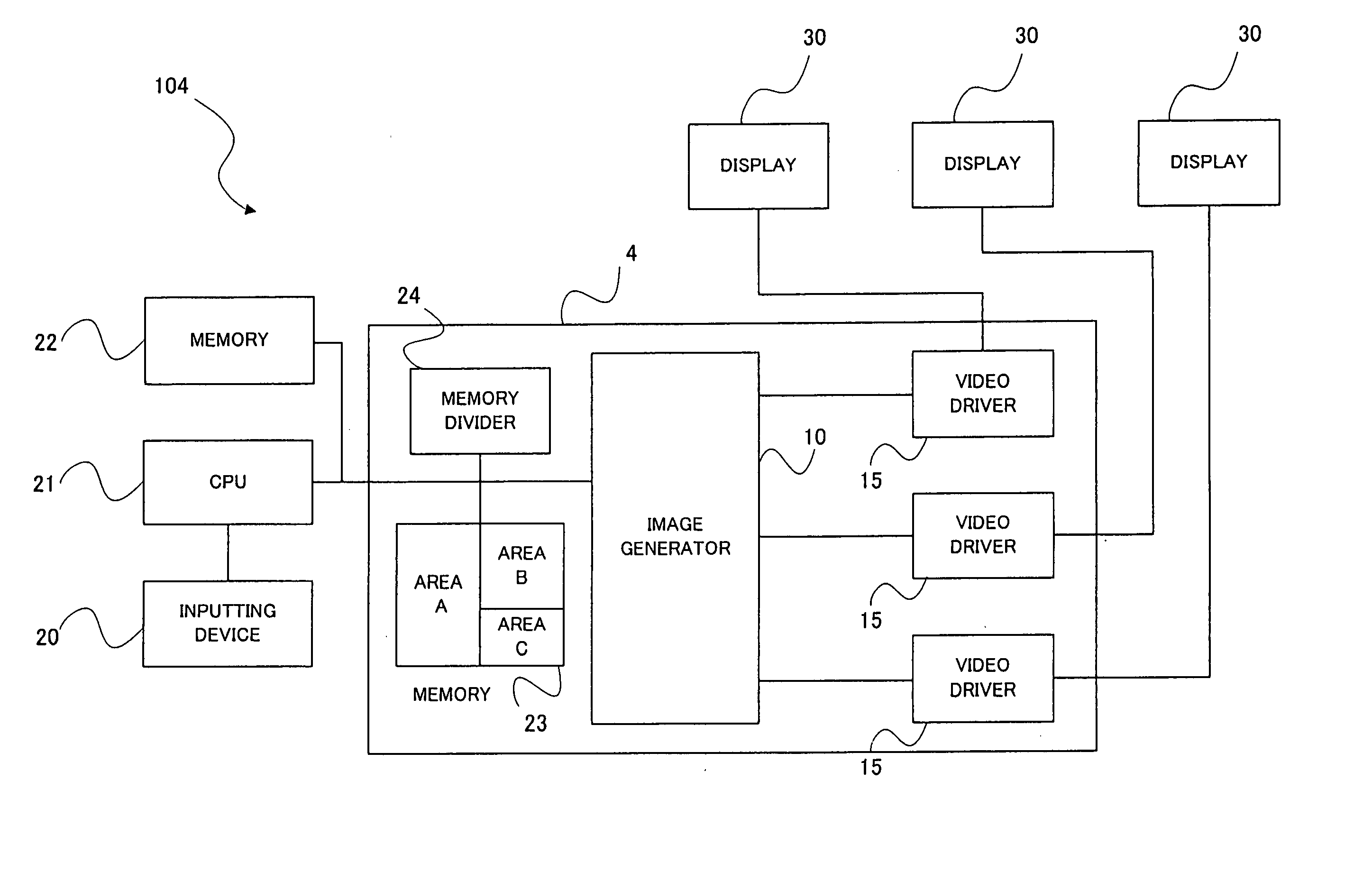
[0022] Furthermore, in an aspect of the drawing apparatus in the aforementioned embodiment, the drawing apparatus has a working area for the video image generating device to generate the plurality of different video signals; and divides the working area into a plurality of record area portions to generate the plurality of different video signals. Then, the signal transmitting device transmits the different video signals generated in the record area portions to the plurality of display devices associated with the different video signals respectively. In this case, for example, each divided working area (each record area portions) corresponds to each display device one-to-one, by providing the divided working areas for each video signal to generate a plurality of video signals to be displayed on a plurality of display devices. Then, the signal transmitting device transmits the generated different video signals to the display devices corresponding to the respective divided working areas, and thereby different video images can be displayed on a plurality of display devices. In this way, the aforementioned division multiplexing device and the identification signal generating device are not essential, resulting in the simple construction of the drawing apparatus.
[0031] According to this aspect, the same video image is relatively easily displayed without changing the construction of drawing apparatus, in a case that the same video image is displayed, instead of displaying different video images on a plurality of display devices.
[0034] Thereby, it is possible to switch display mode between the same video image and different video images for a plurality of display devices, without increasing the processing load of the drawing apparatus.
[0040] According to an embodiment of the computer program product of the invention, the aforementioned embodiment of the drawing apparatus of the invention may be embodied relatively easily, by reading and running the computer program product from a record medium, such as a ROM, a CD-ROM, a DVD-ROM, a hard disk and so on, storing the computer program therein / thereon, or by downloading the computer program product to the computer via the communication device and running it. The computer loaded with the computer program product according to the present embodiment can realize the same operation as in the aforementioned embodiment according to the drawing apparatus of the invention.

Problems solved by technology

In this case, the drawing performance cannot be utilized effectively.
Additionally, preparing a plurality of drawing apparatuses involves the increase in the product weight, and the power consumption greater than necessary.
Furthermore, the drawing apparatus is very expensive due to its high performance ability in graphic processings.
Therefore, preparing a plurality of drawing apparatuses raises considerably the product cost.
Still further, it is difficult to design software for parallel operations of a plurality of drawing devices.

Method used


Image

  • Drawing apparatus and method, computer program product, and drawing display system
  • Drawing apparatus and method, computer program product, and drawing display system
  • Drawing apparatus and method, computer program product, and drawing display system

Examples


embodiments

(Embodiments)

[0062] With reference to drawings, the drawing apparatus and drawing method, as well as the computer program product, of the present invention will now be discussed along with its embodiments. Incidentally, the drawing apparatus in embodiments is embodied in a GDC (Graphic Display Controller), capable of generating graphic images directly on the hardware circuit, under control of the CPU, or in the CPU circuit, and the like. The explanation will be made on this drawing apparatus, as a specific example of the drawing apparatus capable of displaying different images on a plurality of display devices.

(First Embodiment)

[0063] Firstly, the first embodiment of the drawing apparatus according to the present invention will be explained, with reference to FIG. 1 to FIG. 10.

(Fundamental Structure of First Embodiment)

[0064] Firstly, the fundamental structure of the drawing apparatus in the first embodiment will be discussed, taking as an example a drawing display system incl...

first embodiment

(Modification of First Embodiment)

[0114] Next, with reference to FIG. 10, an explanation will be made on a modification of the drawing apparatus according to the first embodiment of the present invention. FIG. 10 illustrates a fundamental construction of the drawing apparatus in this modification. As shown in FIG. 10, the drawing apparatus la in this modification is provided with: video image / identification signal generator 10a; the switch 11; the video signal division multiplexer 12; and the video driver 15. A drawing display system 101a is provided with: in addition to the drawing apparatus la, the input device 20; the CPU 21; the memory 22 and a plurality (three in this modification) of displays 30, 30, 30 corresponding to the aforementioned display device.

[0115] Particularly, the drawing apparatus 1a in this modification has the video image / identification signal generator 10a, for generating the video signal on which the identification signal as explained with reference to FIG....

second embodiment

(Exemplary Operation of Second Embodiment)

[0126] Next, with reference to FIG. 12, an explanation will be made on an exemplary operation of the drawing apparatus according to the second embodiment. FIG. 12 illustrates schematically and conceptually the video signal generated by the drawing apparatus according to the second embodiment.

[0127] The operation of the drawing apparatus according to the second embodiment is the same as that of the drawing apparatus according to the first embodiment. That is, due to the operation shown in the flow chart of FIG. 3, a plurality of different video signals is generated, and divided and multiplexed and then transmitted with the identification signal to each display.

[0128] That is, the video output of each display is checked (step S11, see FIG. 3), and it is judged whether or not the video request of each display is for displaying the same video image on three displays 30, 30, 30 (step S12, see FIG. 3).

[0129] As a result of this judgement, if th...


PUM


Abstract

A drawing apparatus for displaying video images on a plurality of display devices respectively, the apparatus is provided with: a video signal generating device for generating a plurality of different video signals; and a signal transmitting device for transmitting each of the plurality of different video signals to the plurality of display devices corresponding to each of the different video signals.

Description

BACKGROUND OF THE INVENTION [0001] 1. Field of the Invention [0002] The present invention relates to a drawing apparatus for and a drawing method of displaying a video image on a plurality of display devices, and relates to a computer program product executable by the drawing apparatus and further relates to a drawing display system. [0003] 2. Description of the Related Art [0004] Drawing apparatuses, such as GDCs (Graphic Display Controllers), capable of generating graphic images directly on hardware circuits, under control of CPUs or in CPU circuits and the like, are used as apparatuses necessary for displaying images on display devices. The drawing apparatuses allow hardware-level image processings, due to their extremely high level and high speed graphic processing performance. For instance, they are likely used in the case that the extremely high level graphic processings are demanded, such as generating high quality CGs (computer graphics) made of a plurality of polygons, or g...

Claims


Application Information

Patent Timeline
IPC IPC(8): G06F3/14G06F3/153G09G5/00H04N5/14
CPCG06F3/1431G09G2340/0435G09G5/39G09G5/006
Inventor ISHIZU, KAZUNORIFUJITA, HIROAKIADACHI, HAJIME
Owner PIONEER CORP
Learn More