
Wireless communication system for detecting location of the node

a communication system and node technology, applied in multiplex communication, instruments, assess restrictions, etc., can solve the problems of difficult to know the position of the sensor node thus placed, difficult to place the sensor in a wide range, etc., and achieve the effect of high connection reliability and enhanced data transmission accuracy

Inactive Publication Date: 2005-06-30
HITACHI LTD
View PDF4 Cites 130 Cited by
  • Summary
  • Abstract
  • Description
  • Claims
  • Application Information

AI Technical Summary

Benefits of technology

[0008] It is therefore an object of this invention to provide a wireless communication system capable of collecting data from a wide range and easily establishing a connection path in a sensor network collecting data from a number of sensor nodes.
[0010] According to the embodiment of this invention, each of the nodes is connected hierarchically, so that a sensor can be placed in a wide range. Furthermore, since the number of hops is small, and a path under a satisfactory condition is selected autonomously, connection reliability is high, and the accuracy of data transmission is enhanced.

Problems solved by technology

Furthermore, a near-field wireless system (e.g., FSK, UWB, ZigBee, etc.) used in a sensor network has a short communication distance, so that it is difficult to place a sensor in a wide range.
Furthermore, when a sensor node can be placed in a wide range, it is difficult to know the position of the sensor node thus placed.

Method used


Image

  • Wireless communication system for detecting location of the node
  • Wireless communication system for detecting location of the node
  • Wireless communication system for detecting location of the node

Examples


Embodiment Construction

[0019] Hereinafter, this invention will be described by way of an embodiment with reference to the drawings.

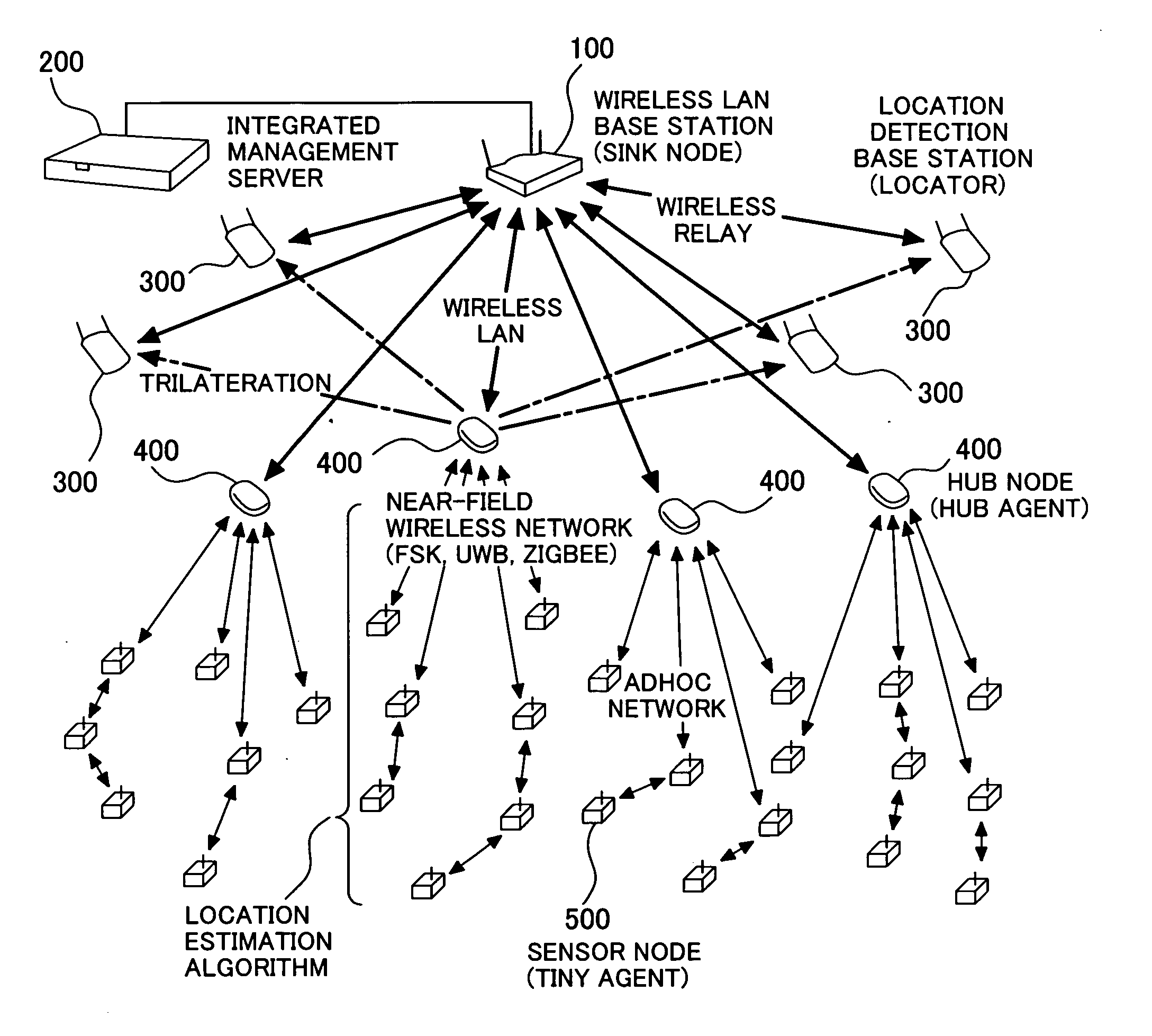
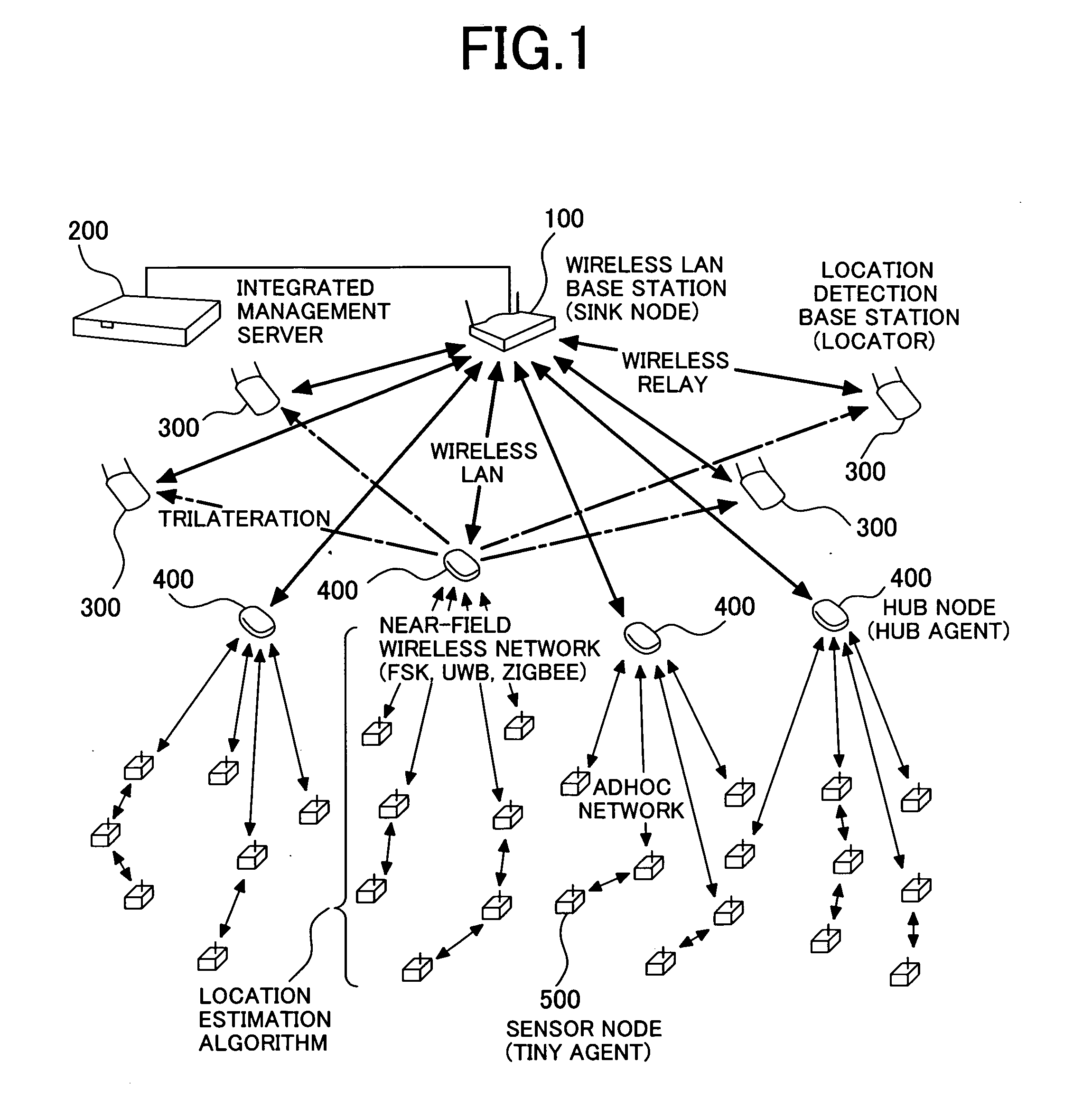
[0020]FIG. 1 is a diagram showing a configuration of a wireless communication system of the embodiment of this invention.

[0021] The wireless communication system of this embodiment comprises a wireless LAN base station 100 as a sink node, hub nodes 400 connected to the wireless LAN base station 100, location detecting base stations (locators) 300 received signals from the hub nodes 400 so as to calculate locations of the hub nodes 400, sensor nodes 500 connected to the hub nodes 400, and an integrated management server 200 integratively managing the wireless communication system.

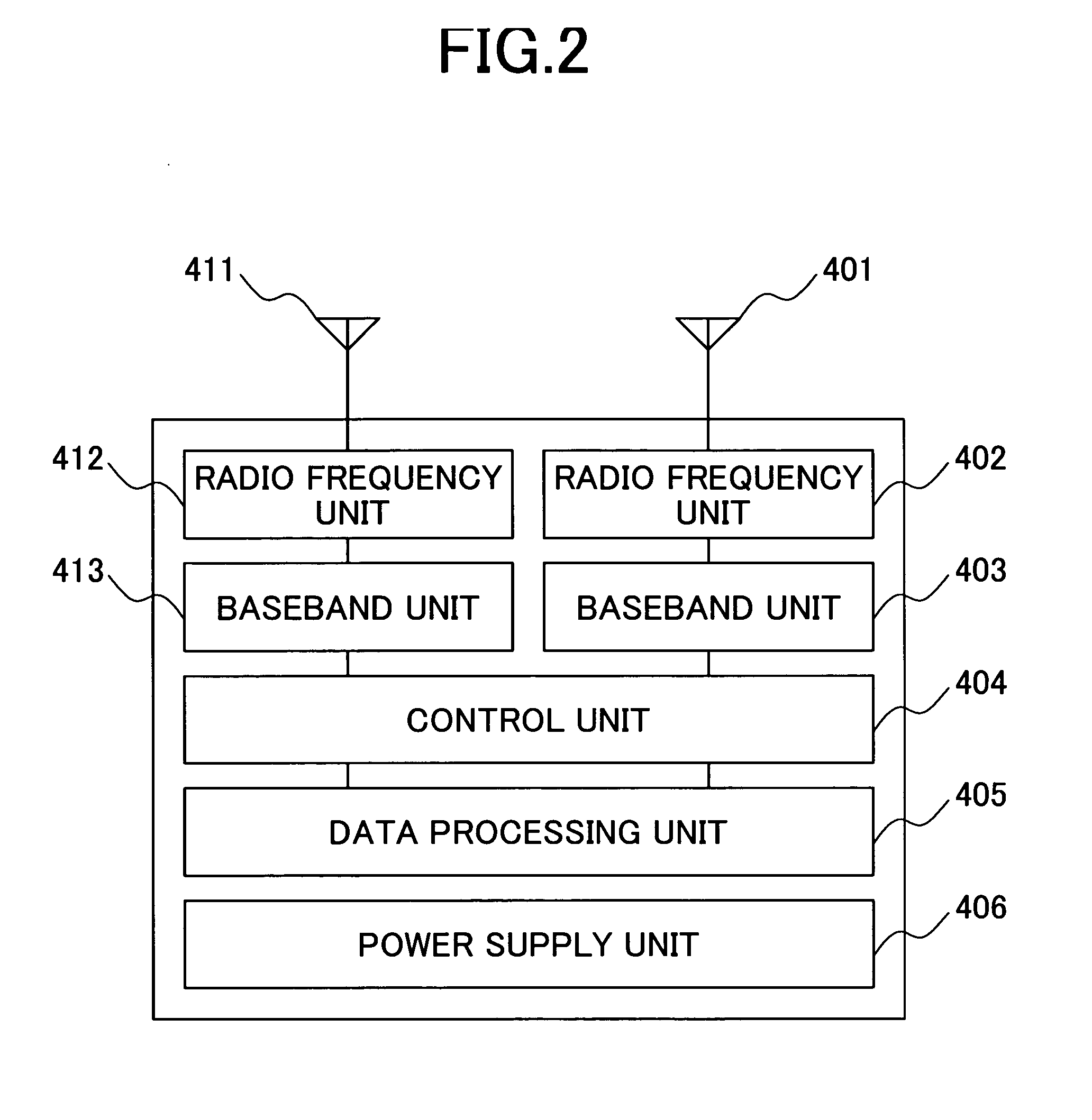
[0022] The sink node 100 is provided on near to the hub nodes 400, and connected to the hub nodes 400 so as to communicate via wireless LAN network. Therefore, the sink node 100 has an antenna, a radio frequency unit, and a unit. A signal received by the antenna is input to the radio frequency baseb...


PUM


Abstract

Provided is a wireless communication system easily establishing a connection path in a sensor network collecting data from a number of sensor nodes. The wireless communication system comprises a base station communicating by a first wireless communication system, plural first nodes communicating by the first wireless communication system and a second wireless communication system, and plural second nodes communicating by the second wireless communication system. The first node transmits the number of hops in the first wireless communication system to the second node. The second node obtains a reception condition of at least one of a signal transmitted by the first node and a signal transmitted by the second node, and selects a upper stage node to connect based on the number of hops in the first wireless communication system, the number of hops in the second wireless communication system, and the obtained reception condition information.

Description

CLAIM OF PRIORITY [0001] The present application claims priority from Japanese application P2003-426282 filed on Dec. 24, 2004, the content of which is hereby incorporated by reference into this application. BACKGROUND OF THE INVENTION [0002] This invention relates to a wireless communication system having a network topology, and in particular, to a construction technology of an ad hoc network such as a sensor network and a location measurement technology of a sensor node. [0003] In a ubiquitous computing society, mobile communication, a wireless LAN of companies and the general public, and a P2P network are combined, whereby a physical world and a virtual world are connected to each other. For a purpose of obtaining a context (action, environment), a sensor network develops. In the sensor network, an infra-network (intensive management) of a upper stage level may be mixed with a P2P network (ad hoc) on a terminal side to construct a complex network. [0004] CHEE-YEE CHONG et al. “Se...

Claims


Application Information

Patent Timeline
Patent Type & Authority Applications(United States)
IPC IPC(8): G01S5/00H04J3/00H04L12/28H04W40/00H04W48/08H04W48/20H04W76/02H04W84/12H04W88/08
CPCH04W40/00H04W48/20H04W48/08H04W40/02H04W84/18
Inventor KATO, TAKESHITAMAKI, TSUYOSHI
Owner HITACHI LTD
Learn More