Six degrees of freedom mirrored cantilever extensometer

a technology of mirrored cantilever and extensometer, which is applied in the field of extensometer, can solve problems such as the difficulty of isolating other components of load, and achieve the effect of reducing the second-order force

Inactive Publication Date: 2005-07-07
INDAL SENSORS & INSTR
View PDF11 Cites 8 Cited by
  • Summary
  • Abstract
  • Description
  • Claims
  • Application Information

AI Technical Summary

Benefits of technology

[0009] The active components of the sensing element are disposed within a housing for protection from moisture, dirt, and other environmental factors. The housing is typically purged with dry, inert gas and i...

Problems solved by technology

Use of taper necessary for uniform strength consideration ca...

Method used


Image

  • Six degrees of freedom mirrored cantilever extensometer
  • Six degrees of freedom mirrored cantilever extensometer
  • Six degrees of freedom mirrored cantilever extensometer

Examples


Embodiment Construction

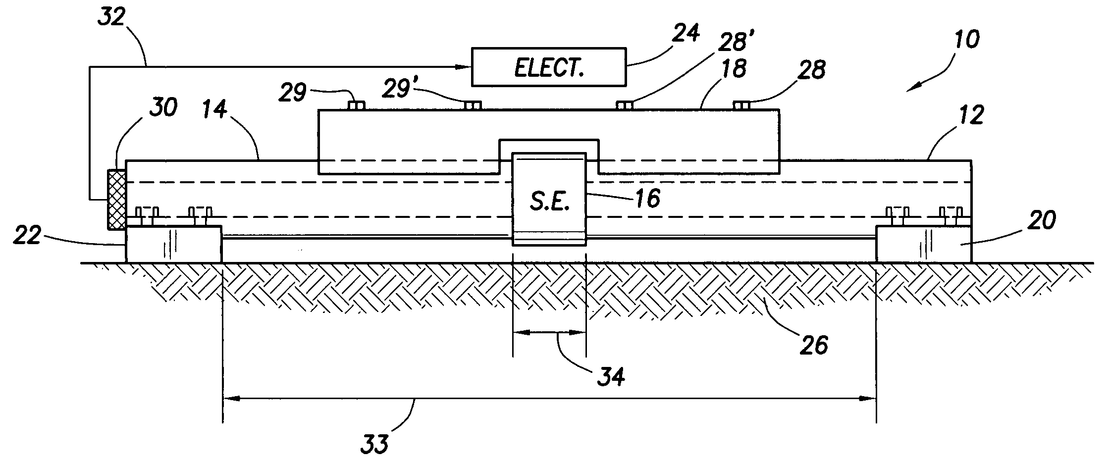
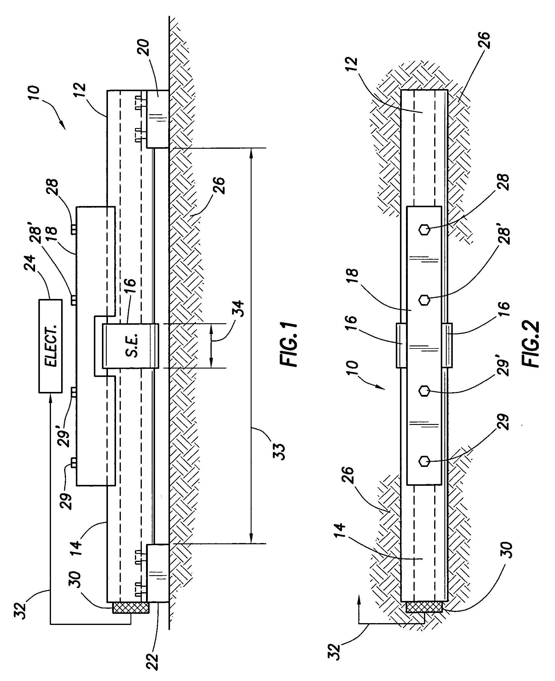
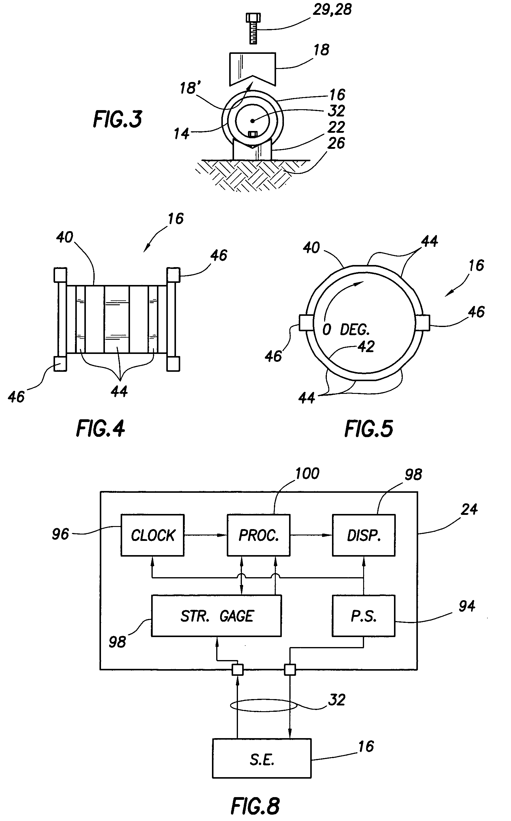
[0020] Attention is directed to FIG. 1, which is a side view of the extensometer system comprising an electronics package 24 and an extensometer 10. Major elements of the extensometer 10 are illustrated. The extensometer comprises opposed cantilever beams 12 and 14 fixed in a mirrored position with respect to a structure 26 thereby isolating and magnifying discrete linear and angular triaxial displacements that are induced by complex loads acting on the structure 26. Each cantilever beam 12 and 14 comprises a fixed end and a free end, wherein the fixed ends are rigidly attached to the structure 26. The free ends of the cantilever beams 12 and 14 are attached to each other through a compliant, linearly elastic sensing element 16 that is distorted by rigid-body motions of the cantilever beams 12 and 14 relative to their attachments to the structure 26.

[0021] Still referring to FIG. 1, the sensing element 16 is capable of first order isolation of signals from discrete components of de...


PUM


Abstract

An extensometer measures and monitors changes in complex loads on a structure. The extensometer comprises opposed cantilever beams fixed in “mirrored” position and aligned with the structure. Each beam has a fixed end and a free end. The fixed end of the cantilever beam is attached to the structure being monitored. The free ends are attached to each other through a compliant, linearly elastic sensing element that is distorted by rigid-body motions of the cantilever beams relative to their attachments to the structure. The sensing element is capable of first order isolation of signals from discrete components of deflections of the structure in proportional response to the strains or stresses on the structure.

Description

FIELD OF THE INVENTION [0001] This invention is directed to an extensometer to measure displacements resulting from forces exerted upon a structure, and more particularly to an extensometer comprising opposed cantilever beams fixed in “mirrored” position with respect to each other, and preferably aligned with the stress / strain axis of interest on the structure (usually the principal axis). This structure and alignment isolates and magnifies discrete linear and angular triaxial displacements that are induced by complex loads acting on the structure. Equivalent strains, stresses, and loads can be calibrated, or calculated from the displacement outputs of the extensometer. BACKGROUND OF THE INVENTION [0002] All physical structures experience complex loads of varying degree. The loads can be relatively constant in magnitude, or change in magnitude with time. Changes can occur over a relatively long period of time from factors such as aging or wear, or can occur over a relatively short p...

Claims


Application Information

Patent Timeline
IPC IPC(8): G01L1/00G01L1/22G01L5/16G01M5/00
CPCG01L1/2218G01L1/2231G01M5/0041G01M5/0025G01L5/161
Inventor DUBLIN, WILBUR LESLIE JR.
Owner INDAL SENSORS & INSTR
Why Eureka
Try Eureka