
Evaporated LaAlO3 films for gate dielectrics

a gate dielectric and laalo3 technology, applied in the direction of semiconductor devices, basic electric elements, electrical equipment, etc., can solve the problems of limiting the physical thickness to which a siosub>2 /sub>layer can be scaled, additional fabrication requirements, and the inability to meet the requirements of siosub>2 /sub>layer replacement, etc., to achieve the effect of determining a suitable replacement for siosub>2 /sub

Inactive Publication Date: 2005-07-07
MICRON TECH INC
View PDF99 Cites 116 Cited by
  • Summary
  • Abstract
  • Description
  • Claims
  • Application Information

AI Technical Summary

Benefits of technology

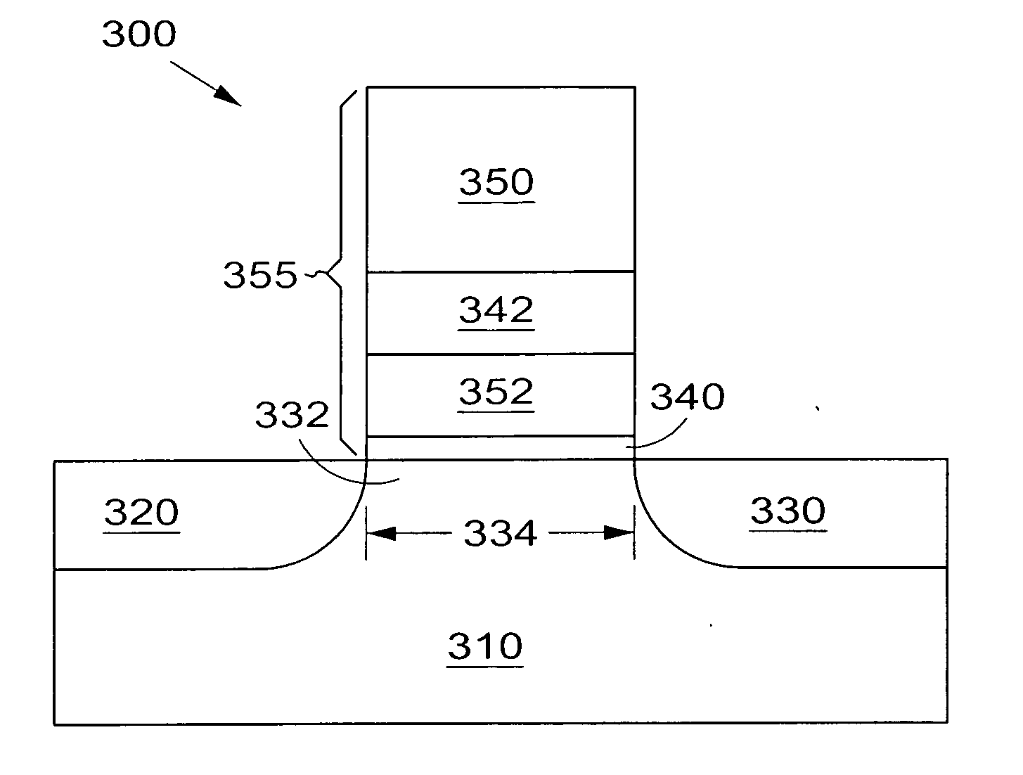
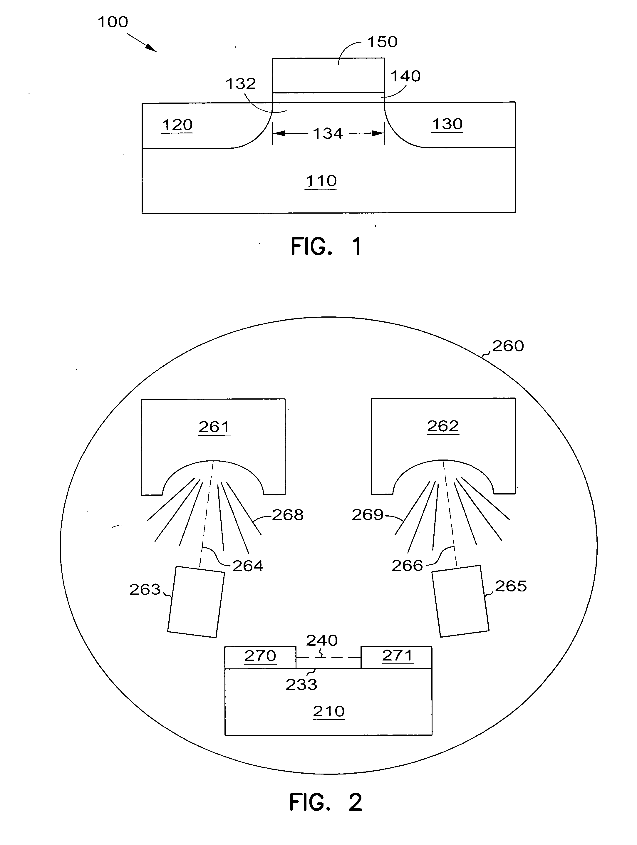
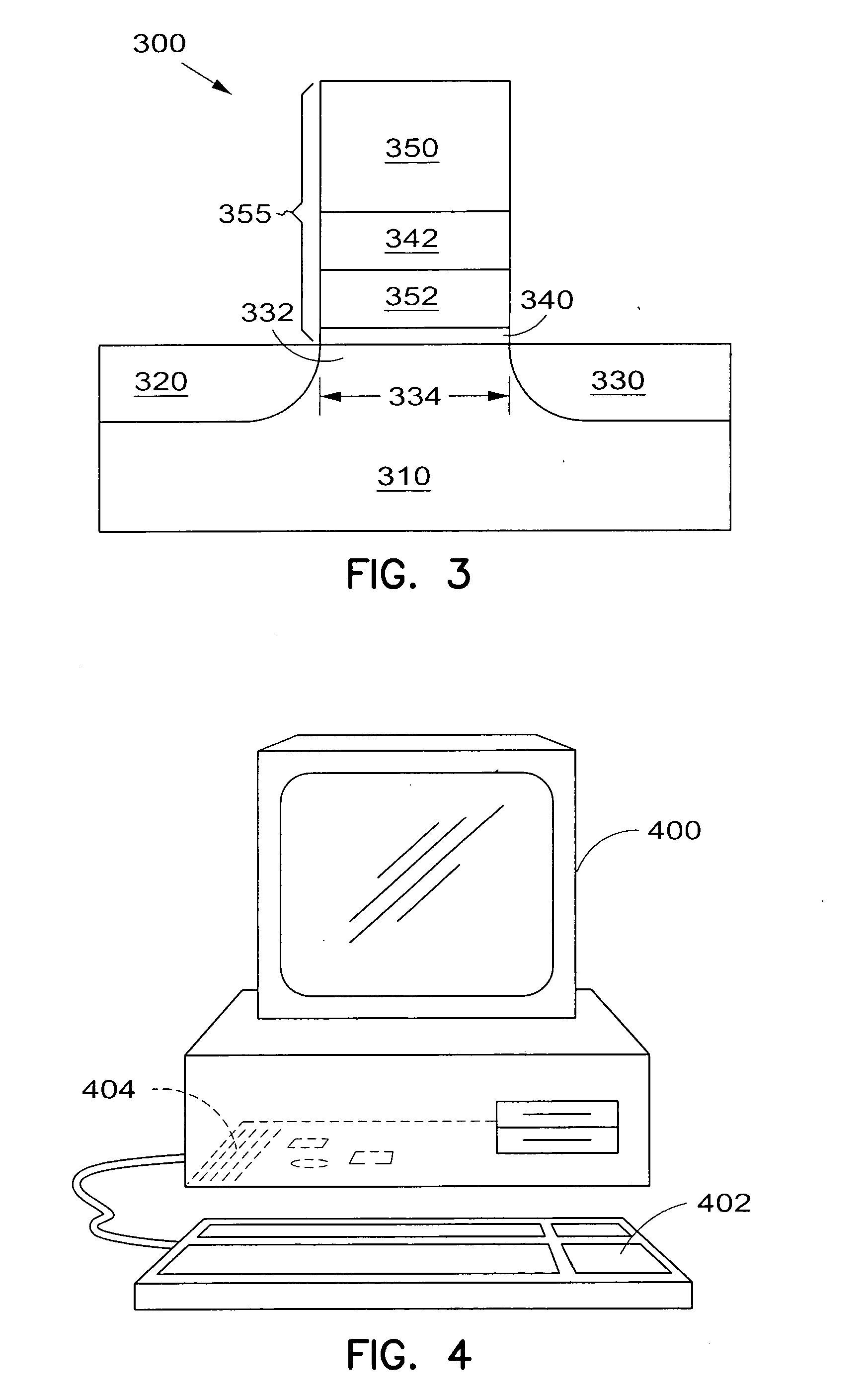
The present invention provides a method for forming a gate dielectric on a transistor body region using a combination of evaporation deposition of Al2O3 and La2O3, controlling the evaporation rates to provide a film composition with a predetermined dielectric constant. This method can be used to form a memory array with transistors having gate dielectrics containing LaAlO3, which can provide reduced voltage levels and improved performance. The invention also provides a transistor with an amorphous gate dielectric containing LaAlO3, which can have a dielectric constant ranging from the dielectric constant of Al2O3 to the dielectric constant of La2O3. The invention also includes a memory array and an information handling system with a processor and memory array containing transistors with amorphous gate dielectrics containing LaAlO3.

Problems solved by technology

Such a small thickness requirement for a SiO2 oxide layer creates additional problems.
This undesirable property sets a limit on the physical thickness to which a SiO2 layer can be scaled.
The thinner equivalent oxide thickness, teq, required for lower transistor operating voltages and smaller transistor dimensions may be realized by a significant number of materials, but additional fabricating requirements makes determining a suitable replacement for SiO2 difficult.

Method used


Image

  • Evaporated LaAlO3 films for gate dielectrics
  • Evaporated LaAlO3 films for gate dielectrics
  • Evaporated LaAlO3 films for gate dielectrics

Examples


Embodiment Construction

[0022] In the following detailed description of the invention, reference is made to the accompanying drawings which form a part hereof, and in which is shown, by way of illustration, specific embodiments in which the invention may be practiced. In the drawings, like numerals describe substantially similar components throughout the several views. These embodiments are described in sufficient detail to enable those skilled in the art to practice the invention. Other embodiments may be utilized and structural, logical, and electrical changes may be made without departing from the scope of the present invention.

[0023] The terms wafer and substrate used in the following description include any structure having an exposed surface with which to form the integrated circuit (IC) structure of the invention. The term substrate is understood to include semiconductor wafers. The term substrate is also used to refer to semiconductor structures during processing, and may include other layers that...


PUM


Abstract

A gate dielectric containing LaAlO3 and method of fabricating a gate dielectric contained LaAlO3 produce a reliable gate dielectric having a thinner equivalent oxide thickness than attainable using SiO2. The LaAlO3 gate dielectrics formed are thermodynamically stable such that these gate dielectrics will have minimal reactions with a silicon substrate or other structures during processing. A LaAlO3 gate dielectric is formed by evaporating Al2O3 at a given rate, evaporating La2O3 at another rate, and controlling the two rates to provide an amorphous film containing LaAlO3 on a transistor body region. The evaporation deposition of the LaAlO3 film is performed using two electron guns to evaporate dry pellets of Al2O3 and La2O3. The two rates for evaporating the materials are selectively chosen to provide a dielectric film composition having a predetermined dielectric constant ranging from the dielectric constant of an Al2O3 film to the dielectric constant of a La2O3 film. In addition to forming a LaAlO3 gate dielectric for a transistor, memory devices, and information handling devices such as computers include elements having a LaAlO3 gate electric with a thin equivalent oxide thickness.

Description

FIELD OF THE INVENTION [0001] The invention relates to semiconductor devices and device fabrication. Specifically, the invention relates to gate dielectric layers of transistor devices and their method of fabrication. BACKGROUND OF THE INVENTION [0002] The semiconductor device industry has a market driven need to improve speed performance, improve its low static (off-state) power requirements, and adapt to a wide range of power supply and output voltage requirements for it silicon based microelectronic products. In particular, in the fabrication of transistors, there is continuous pressure to reduce the size of devices such as transistors. The ultimate goal is to fabricate increasingly smaller and more reliable integrated circuits (ICs) for use in products such as processor chips, mobile telephones, or memory devices such as DRAMs. The smaller devices are frequently powered by batteries, where there is also pressure to reduce the size of the batteries, and to extend the time between...

Claims


Application Information

Patent Timeline
Patent Type & Authority Applications(United States)
IPC IPC(8): H01L21/28H01L29/51
CPCH01L21/02178H01L21/02192H01L21/02194H01L29/517H01L21/28185H01L21/28194H01L21/02269
Inventor AHN, KIE Y.FORBES, LEONARD
Owner MICRON TECH INC
Learn More