Under-vehicle aerodynamic efficiency improvement device

a technology for aerodynamic efficiency improvement and under-vehicle, which is applied in the direction of roofs, transportation and packaging, vehicle arrangements, etc., can solve the problems of increasing fuel consumption

Inactive Publication Date: 2005-07-07
ULAND WILLIAM BURLEY
View PDF17 Cites 60 Cited by
  • Summary
  • Abstract
  • Description
  • Claims
  • Application Information

AI Technical Summary

Problems solved by technology

This device is aerodynamically designed to correct airflow patterns under a vehicle prone to develop or create turbulent airflow patterns which increases aerodynamic drag on the vehicle which results in increased fuel consumption.

Method used


Image

  • Under-vehicle aerodynamic efficiency improvement device
  • Under-vehicle aerodynamic efficiency improvement device

Examples


Embodiment Construction

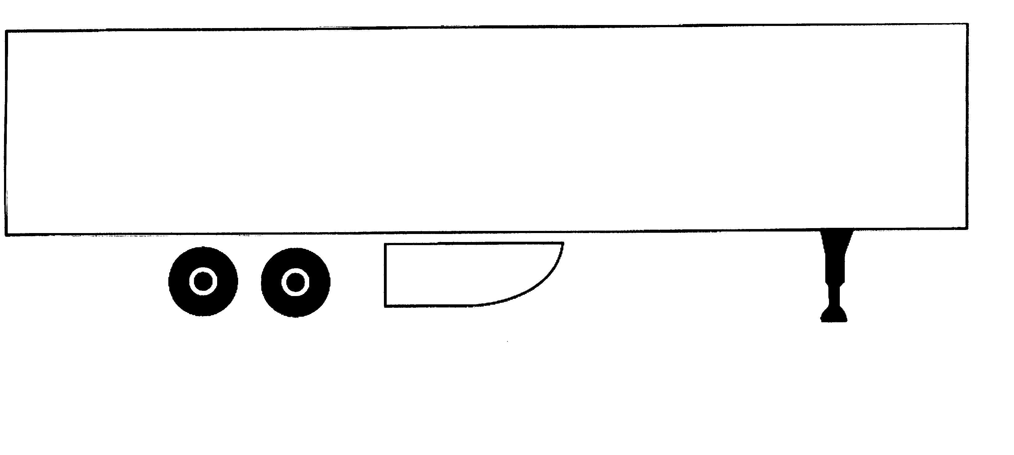
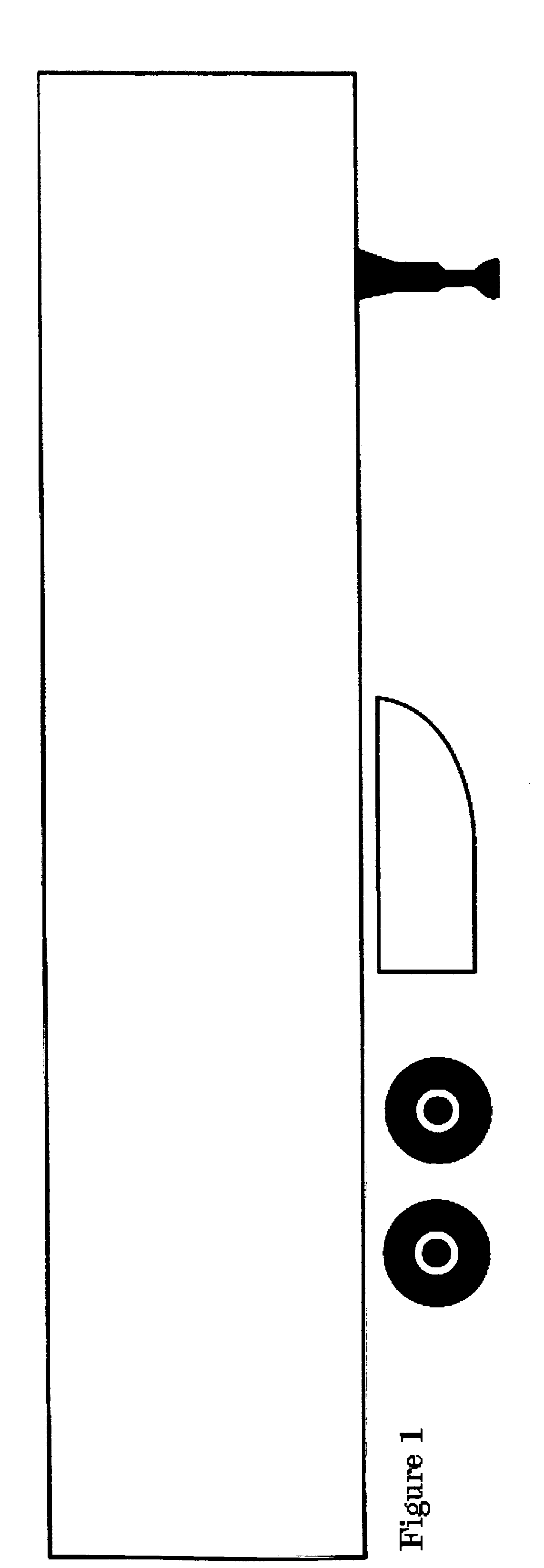
[0006] The device is positioned under a vehicle that has open space ahead of the rear axle assembly. The device is designed to improve the flow of air from the bottom and sides of the vehicle.

[0007] The device can be made of several different materials including, but not limited to: ABS plastic, polystyrene, polyethylene, cross-linked polyethylene, resin-filled glass, glass fiber matting, chopped fiber matting, carbon fiber matting, and other materials of a like nature used in similar manufacturing processes. The use of these types of materials will allow for simple manufacturing of the device. The type of material used will be based on the shape, size, and cost of manufacturing, as well as structural strength needed, impact absorption and deflection ability, ultraviolet light resistance, and anticipated length of time the device can remain in service in a particular application. The manufacturing of this device may consist of one of the following present known techniques or a tech...


PUM


Abstract

This invention relates to a device used to cover the chassis of a vehicle, mounted forward of the rear axle assembly(ies) to smooth and enhance the flow of air from under and around the area forward and to the sides of the rear axle assembly(ies). This invention also acts as a protective barrier for the chassis of the vehicle utilizing this device.

Description

BACKGROUND OF INVENTION / TECH FIELD [0001] The present invention relates to a device and the component parts used to cover portions or sections of a vehicle, motorized, or pulled in combination, to improve aerodynamic efficiency. [0002] Most vehicles manufactured today are designed to improve aerodynamic efficiency by the shaping of external vehicle surfaces to reduce aerodynamic drag, thereby reducing fuel consumption. Manufacturers of vehicles use computers, full scale models, and scaled down models to determine optimum airflow over and around the vehicle and its external components. [0003] This invention addresses the problem of airflow under a vehicle with an exposed undercarriage and axle assembly, such as a truck-trailer combination vehicle, a box van, or an extended wheelbase truck. The airflow problems encountered by these vehicles open undercarriage increase fuel consumption by causing an increase in aerodynamic drag. BRIEF SUMMARY [0004] This invention is intended to be a c...

Claims


Application Information

Patent Timeline
Patent Type & Authority Applications(United States)
IPC IPC(8): B62D35/02
CPCB62D35/02Y02T10/82Y02T10/88
Inventor ULAND, WILLIAM BURLEY
Owner ULAND WILLIAM BURLEY
Why Eureka
Try Eureka