Friction stir welded hollow airfoils and method therefor

a friction stir welding and hollow airfoil technology, which is applied in the direction of non-electric welding apparatus, waterborne vessels, machines/engines, etc., can solve the problems of inability to reliably join the alloy of choice, the difficulty or impossible to join the alloy by conventional fusion welding techniques, and the tedious and inefficient method of gun drilling

Inactive Publication Date: 2005-11-17
GENERAL ELECTRIC CO
View PDF14 Cites 106 Cited by
  • Summary
  • Abstract
  • Description
  • Claims
  • Application Information

AI Technical Summary

Problems solved by technology

The alloys of choice, e.g. most 2000- and 7000-series aluminum alloys, may be difficult or impossible to join by conventional fusion welding techniques.
Gun drilling is a tedious and inefficient method for removing the maximum core material to optimize weight reduction.
On the other hand, pocket milling followed by adhesive bonding of a cover has the disadvantage of excessive adhesive bond quality variability, tedious preparation and processing for adhesive bonding success, excessive lap joint widths to obtain adequate adhesive bond strength, and inability to reliably seal the internal pocket from the external environment resulting in excessive susceptibility to undetected internal corrosion and / or stress corrosion cracking over time.

Method used


Image

  • Friction stir welded hollow airfoils and method therefor
  • Friction stir welded hollow airfoils and method therefor
  • Friction stir welded hollow airfoils and method therefor

Examples


Embodiment Construction

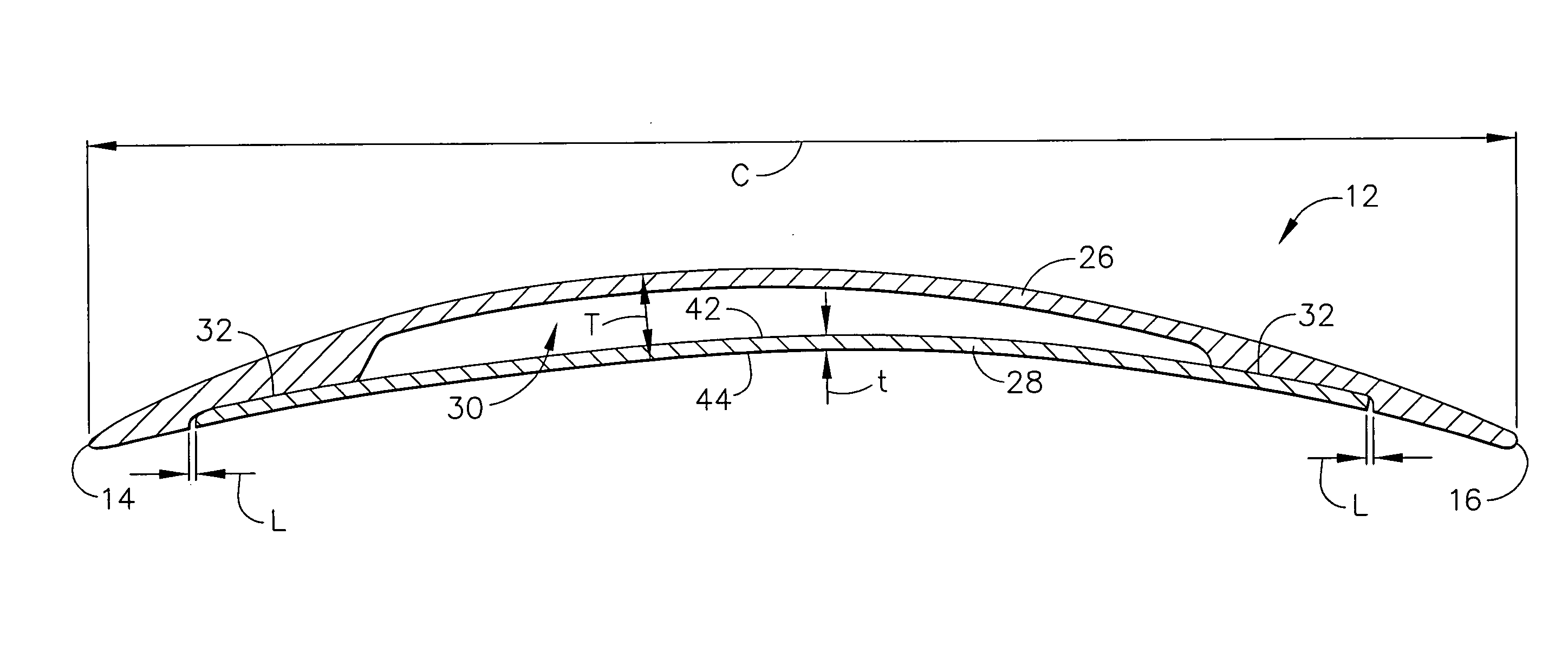
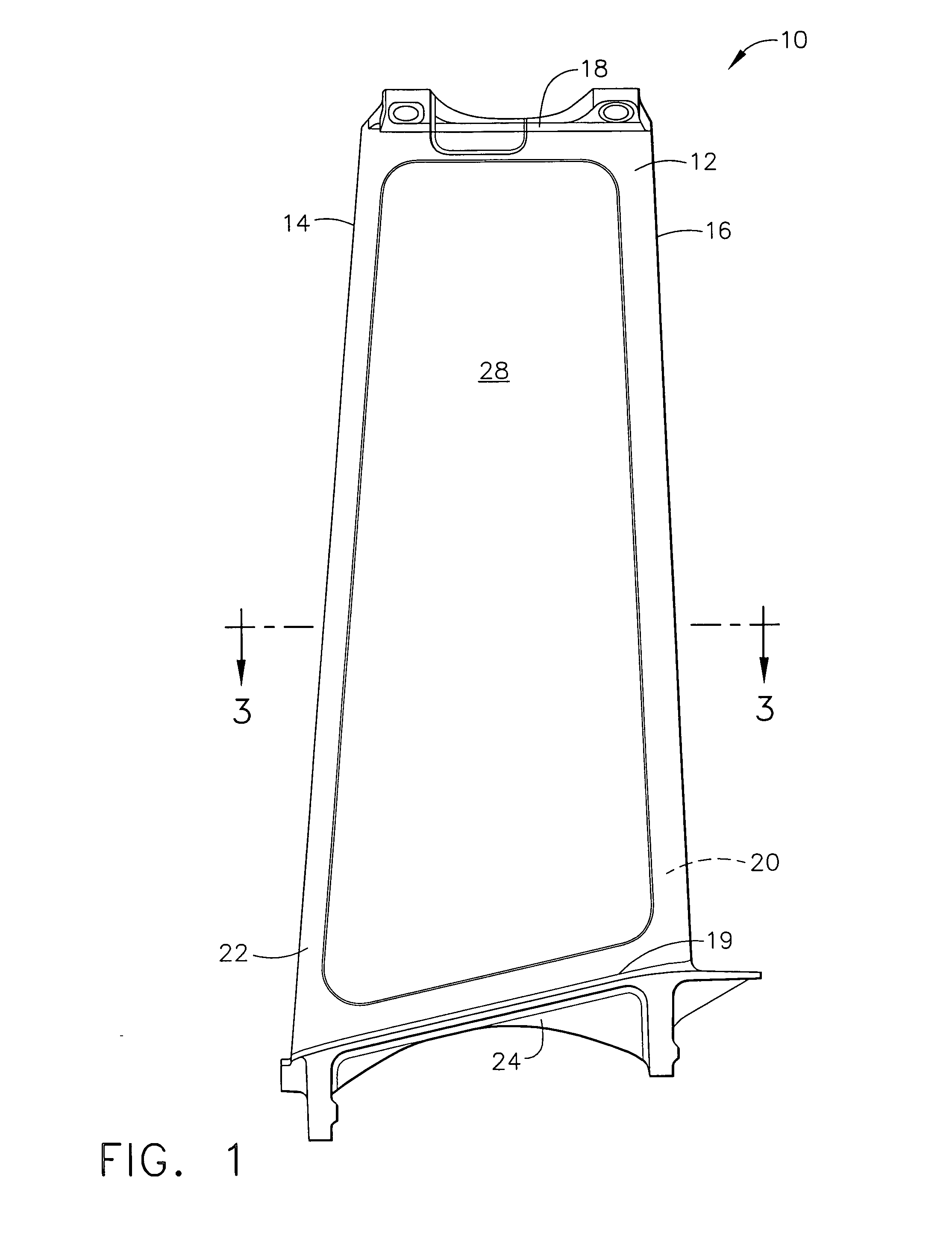
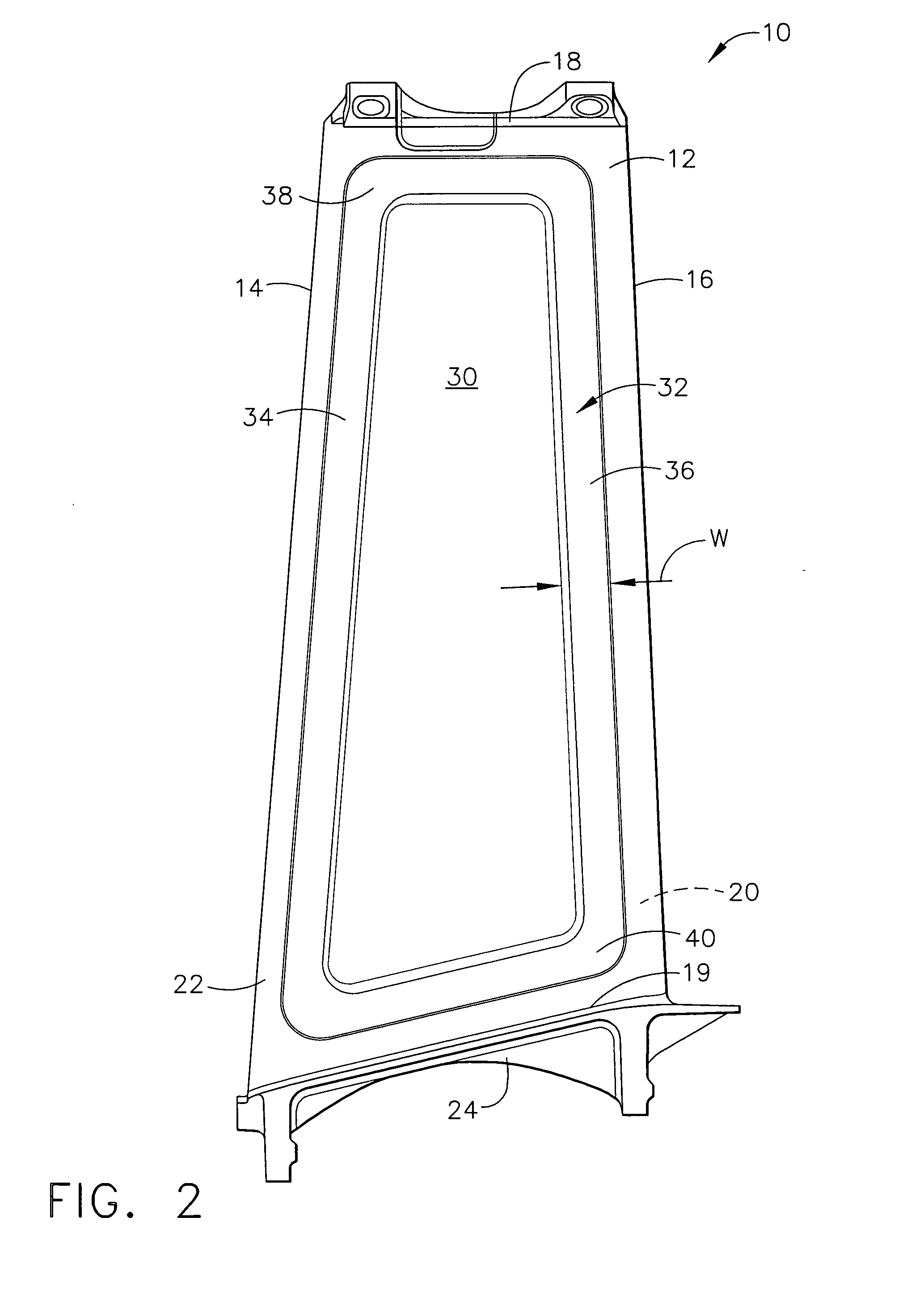
[0021] Referring to the drawings wherein identical reference numerals denote the same elements throughout the various views, FIGS. 1-3 depict an exemplary fan outlet guide vane 10 for a gas turbine engine. The present invention is equally applicable to the construction of other types of hollow components, such as rotating turbine blades, frame struts, and the like. The outlet guide vane 10 comprises an airfoil 12 having a leading edge 14, a trailing edge 16, a tip 18, a root 19, a convex suction side 20, and a concave pressure side 22. An arcuate inner platform 24 is attached to the root 19 of the airfoil 12.

[0022] The illustrated airfoil 12 has an overall thickness T of about 2.54 cm (1 in.) and a chord length C of about 24 cm (9.5 in.) The airfoil 12 is assembled from a body 26 and a cover 28. The body 26 and the cover 28 are both made from a material with suitable strength and weight characteristics for the intended application. One suitable alloy is a 7000 series aluminum alloy...


PUM

PropertyMeasurementUnit
widthaaaaaaaaaa
thicknessaaaaaaaaaa
diameteraaaaaaaaaa

Abstract

A hollow component for gas turbine engine, for example an outlet guide vane, is assembled from a body having at recessed pocket formed therein, and an aerodynamic cover bonded over the pocket. Both the cover and the body are constructed from materials which are not readily fusion weldable. The cover is attached to the body by a solid state bonding process, for example friction stir welding. The hollow component may also be built up from multiple individual components which are bonded to each other by a solid state bonding process such as friction stir welding.

Description

BACKGROUND OF THE INVENTION [0001] This invention relates generally to hollow components for gas turbine engines and more particularly to hollow airfoils constructed by friction stir welding. [0002] Aluminum forgings in various alloy compositions are commonly used for gas turbine engine components, for example non-rotating airfoils in the fan and compressor. Such airfoils often have a hollow cross-section to minimize their weight. The alloys of choice, e.g. most 2000- and 7000-series aluminum alloys, may be difficult or impossible to join by conventional fusion welding techniques. [0003] Therefore, prior art methods for producing hollow airfoils involve gun drilling to remove core material, or pocket milling followed by adhesive bonding of a cover sheet over the milled pocket. The pocket may or may not be filled with honeycomb material, and may or may not incorporate stiffener ribs for improved load carrying capabilities and / or fatigue resistance. [0004] Gun drilling is a tedious an...

Claims


Application Information

Patent Timeline
Patent Type & Authority Applications(United States)
IPC IPC(8): B23K20/12F01D9/02B23K103/10F01D5/14F02C7/00F04D29/32F04D29/54
CPCB23K20/122B23K2201/001F05D2300/121F05B2230/239F05D2230/232F01D5/147B23K2101/001
Inventor HELDER, EARL CLAUDETRAPP, TIMOTHY JOSEPHKELLEY, JOHN ROBERTTUDOR, COURTNEY JAMESBUDINGER, VICKY S.
Owner GENERAL ELECTRIC CO
Why Eureka
Try Eureka