Multi-pulse converter circuits

a converter circuit and multi-pulse technology, applied in the direction of ac-dc conversion, ac-electronic conversion, electric variable regulation, etc., can solve the problems of distortions that can give rise to harmonic variations in voltage, de-rating the maximum capacity of power sources, and addition of distribution losses, so as to reduce total harmonic distortion

Active Publication Date: 2005-07-07
SAFRAN POWER UK
View PDF1 Cites 52 Cited by
  • Summary
  • Abstract
  • Description
  • Claims
  • Application Information

AI Technical Summary

Benefits of technology

[0022] According to a second aspect of the present invention there is provided a method of reducing total harmonic distortion arising from an AC to DC converter, the method comprising: providing first and second three phase passive rectifiers in series, with the second rectifier being supplied via a delta connected transformer and the first rectifier being supplied by connection to a star connected transformer or via series connection to the primary windings of the

Problems solved by technology

If the generator is connected to a load with a significant reactive component then the relationship between the current and voltage becomes altered and the current starts to move out of phase with the voltage thereby giving rise to additional distribution losses and also de-rating the maximum capacity of the power source.
Furthermore, if the load is non-linear then it tends to draw a distorted current (i.e. not sinusoidal current) from the generator.
These distortions can give rise to harmonic variations in voltage which are seen by other loads connected to the generator.
These distortions may affect the performance of these other loads, as well as degrading the

Method used


Image

  • Multi-pulse converter circuits
  • Multi-pulse converter circuits
  • Multi-pulse converter circuits

Examples


Embodiment Construction

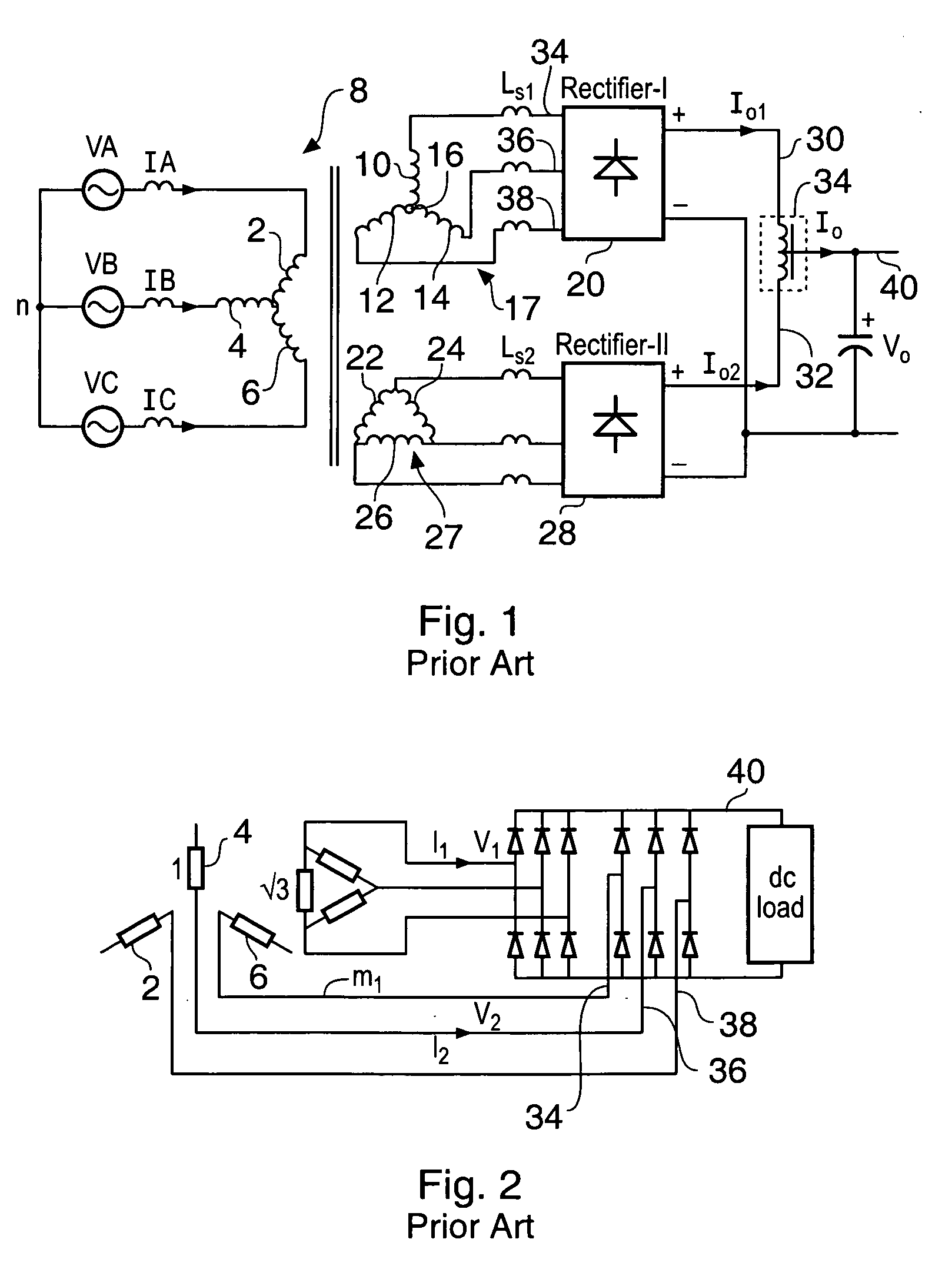
[0047] The arrangement shown in FIG. 1 is that of a prior art twelve pulse rectifier. A three phase supply comprising phase A having a voltage VA and a current IA and phases B and C similarly designated are supplied to star connected windings 2, 4 and 6 of a transformer generally designated 8. It is common for the phases to be referred to as “red”, “yellow” and “blue”, and designated by R, Y and B respectively where red is the zero phase, yellow is the 120° phase and blue is the 240° phase. Both conventions will be used here with A=red, B=yellow and C=blue. The transformer has two sets of secondary windings. A first set of windings 10, 12 and 14 are also connected in a star configuration, i.e. the windings are connected to a common node 16 and for simplicity may be referred to as a “star” windings 17. Outputs of the windings 10, 12 and 14 are supplied to a first rectifier assembly 20 which has the configuration shown in FIG. 5. A second set of windings 22, 24 and 26 are connected in...


PUM


Abstract

An AC to DC converter with harmonic suppression is provided. The harmonic suppression is provided by forcing an instantaneous current conflict between series connected rectifier bridges 54, 80, such that a voltage waveform at 6 times the AC supply frequency of the AC supply is automatically generated. This waveform is then injected via a injection circuit to give harmonic cancellation.

Description

FIELD OF THE INVENTION [0001] The present invention relates to a multi-pulse converter circuit for performing conversion between an alternating current and a direct current. BACKGROUND OF THE INVENTION [0002] A typical power distribution system comprises a generator connected via some distribution network to one or more loads. The generator is typically a multiphase generator and the voltage output on each phase is nominally sinusoidal. If the generator supplies a purely resistive load, then the current drawn from the generator will also be sinusoidal, and is also in phase with the voltage. If the generator is connected to a load with a significant reactive component then the relationship between the current and voltage becomes altered and the current starts to move out of phase with the voltage thereby giving rise to additional distribution losses and also de-rating the maximum capacity of the power source. Furthermore, if the load is non-linear then it tends to draw a distorted cu...

Claims


Application Information

Patent Timeline
IPC IPC(8): H02M1/00H02M1/12H02M1/42
CPCH02M1/12H02M1/4216Y02B70/126H02M7/10H02M1/4233Y02B70/10
Inventor TRAINER, DAVIDFORSYTH, ANDREW JOHNCHIVITE-ZABALZA, FRANCISCO JAVIER
Owner SAFRAN POWER UK
Why Eureka
Try Eureka