Fabrication of samples having predetermined material conditions

Active Publication Date: 2005-07-07
JENTEK SENSORS
View PDF15 Cites 10 Cited by
  • Summary
  • Abstract
  • Description
  • Claims
  • Application Information

AI Technical Summary

Benefits of technology

[0007] In one embodiment of the invention, a sample having a predetermined material condition is fabricated by positioning a sensor near the material surface, measuring the response of the sensor as the material is processed to change the material condition, and then stopping the processing once the material condition reaches a predetermined level. The sensor remains proximate to the material surface for substantial periods of time to monitor progression of the change in the material condition. The material condition is determined from the sensor response using a predetermined correlation, which can be derived from empirical measurements on other samples or by a model calculation or simulation that accurately predicts the sensor response to the material condition. In one embodiment of the invention, the material condition reflects the presence of a crack and the predetermined level is a size of the crack. In various embodiments of the invention, particularly for relatively conductivity materials, the sensor may be a magnetic field based eddy current sensor or sensor array. In another embodiment of the invention, the sensor may be flexible and conform to the material surface.
[0011] In yet another embodiment of the invention, a matrix of samples is fabricated. This is accomplished by positioning a sensor near the material surface, measuring the response of the sensor as the material is processed to change the material condition, stopping the processing once the material condition reaches a predetermined level, and repeating this process multiple times. In one embodiment of the invention, the same predetermined level for the material condition is used to create multiple samples for nominally similar conditions. This allows a probability density function to be generated, which relates the sensor response to the material condition and allows the uncertainty distribution in the material condition to be assessed. This in turn can be used to assess the capability of the sensor to predict other dependent functions, such as the remaining life for the sample. In another embodiment of the invention, the processing is stopped for a range of predetermined levels. In yet another embodiment of the invention, the material is preconditioned prior to processing, so that the matrix contains a broader range of material variations. In one embodiment of the invention, the material condition may be fatigue damage and in another the preconditioning may be shot peening. In different embodiments of the invention, the matrix of samples may be used as a training set for training the sensor response or as a test set for the evaluation of different sensing methods. In an alternative embodiment of the invention, the matrix design or the distribution of predetermined material condition levels may be based on the statistics used in probability of detection studies.

Problems solved by technology

These material conditions include damage, such as the formation of cracks, and damage precursor states, such as the relaxation of residual stresses.
A related material condition that may be monitored during processing is thermal damage.

Method used


Image

  • Fabrication of samples having predetermined material conditions
  • Fabrication of samples having predetermined material conditions
  • Fabrication of samples having predetermined material conditions

Examples


Embodiment Construction

[0033] A description of preferred embodiments of the invention follows.

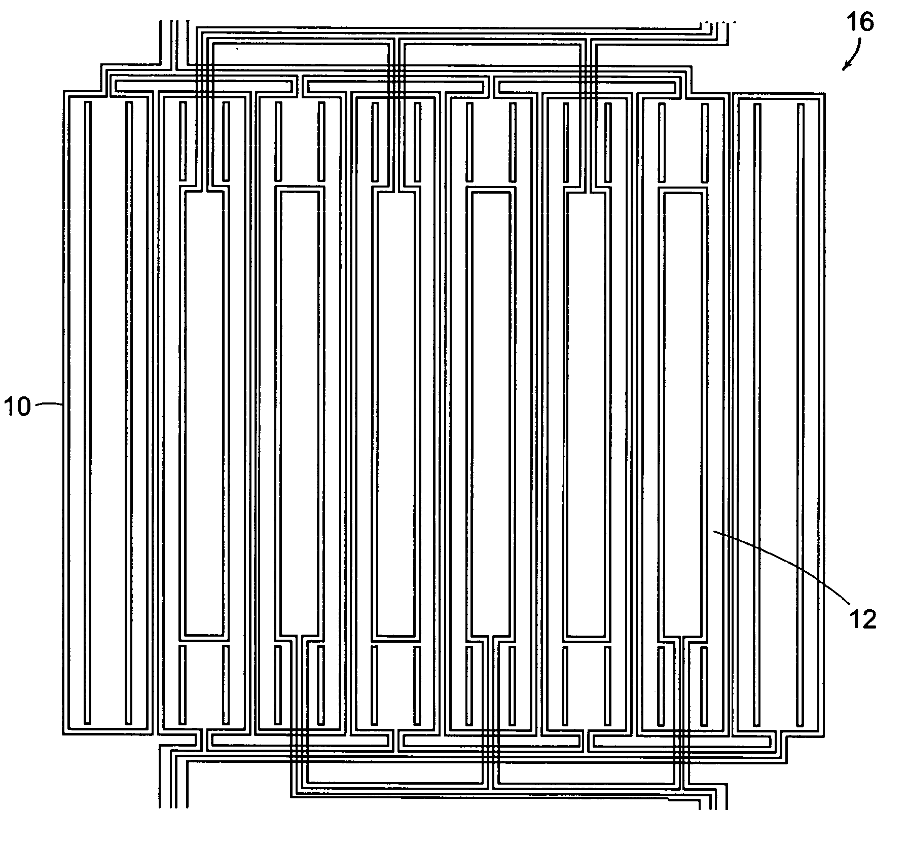
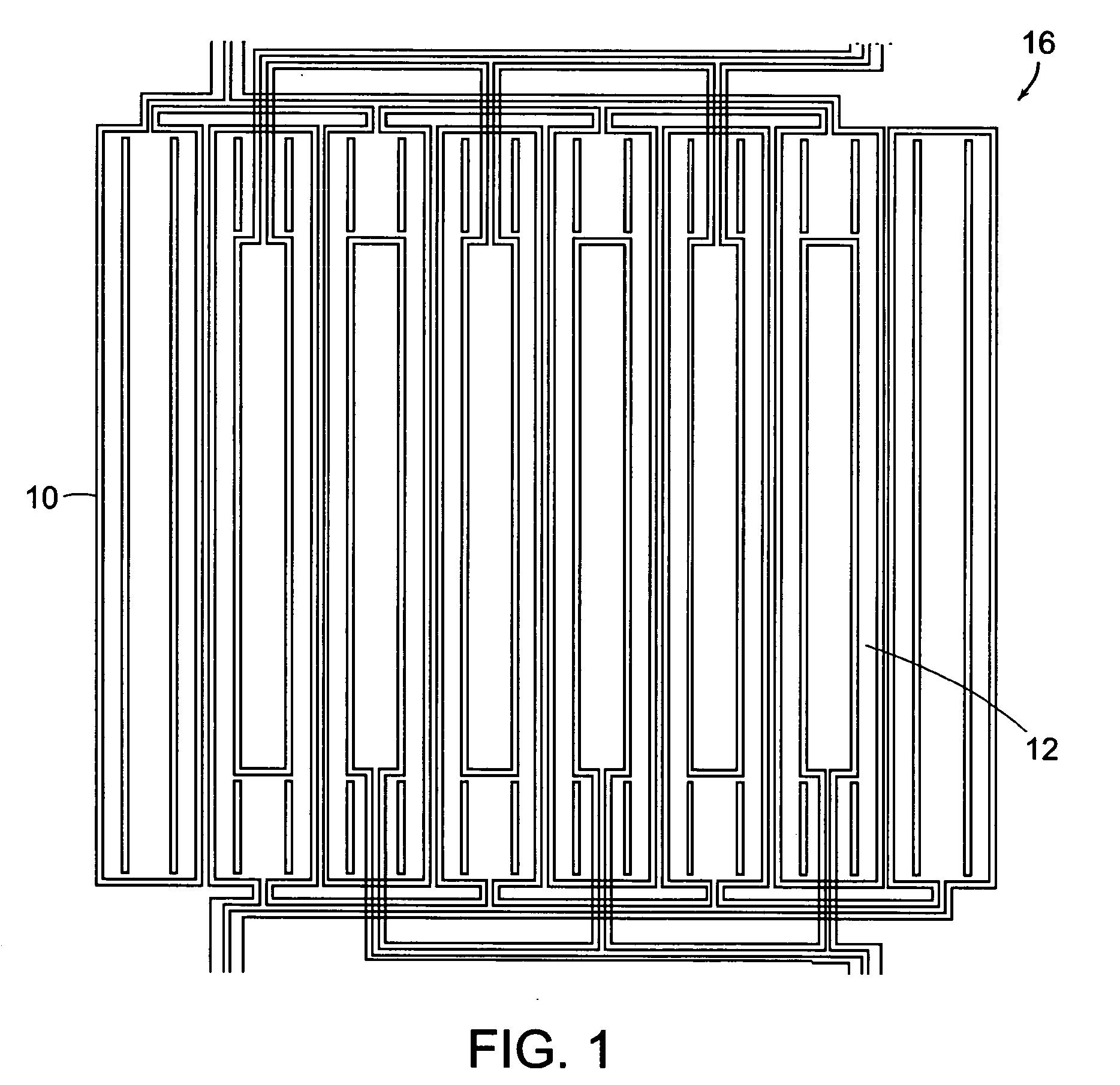
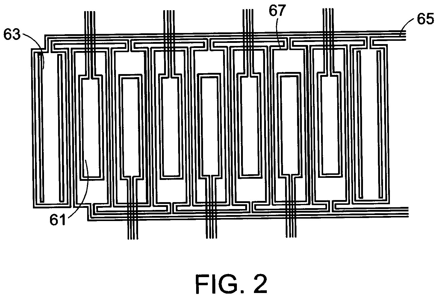
[0034] This application is directed toward the use of sensor and sensor arrays during monitoring of fatigue damage to create reference samples and standards having real fatigue cracks. These standards can be used for sensor standardization in the field and reliability studies for validating sensors or measurement methods. One objective may be to generate specimens with realistic cracks under conditions as close to reality as feasible, and even to generate conditions of interest in actual components, if necessary. Conditions of interest may include cracks in holes, on curved surfaces, on shot peened surfaces, in and under coatings and at buried surfaces. One embodiment of the invention uses permanently mounted sensors, such as MWM®-Array eddy current sensors, to detect crack initiation and monitor crack growth. These sensors have been used in fatigue tests of coupons and components as well as full-scale fatigue t...


PUM


Abstract

Fabrication of samples having material conditions or damage representative of actual components inspected by nondestructive testing involves sensors placed near or mounted on the material surface, such as flexible eddy current sensors or sensor arrays, to monitor the material condition while the sample is being processed. These sample typically have real cracks in or around holes, on curved surfaces, in and under coatings, and on shot peened or otherwise preconditioned surfaces. Processing, such as mechanical or thermal loading to introduce fatigue damage, is stopped once the material condition reaches a predetermined level.

Description

RELATED APPLICATION(S) [0001] This application claims the benefit of U.S. Provisional Application Nos. 60 / 520,000, filed Nov. 14, 2003, and 60 / 569,216, filed May 7, 2004. The entire teachings of the above applications are incorporated herein by reference.GOVERNMENT SUPPORT [0002] The invention was supported, in whole or in part, by a Contract Number F09650-02-C-0516 from the Department of the Air Force and by Contract Number N68335-03-C-0123 from the Department of the Navy. The Government has certain rights in the invention.BACKGROUND OF THE INVENTION [0003] This application addresses nondestructive materials characterization and, particularly fabrication of reference samples for validating inspection methods and for establishing correlations between sensor responses and actual material condition. The nondestructive material characterization provides a quantitative, model-based characterization of surface, near-surface, and bulk material condition for flat and curved parts or compon...

Claims


Application Information

Patent Timeline
IPC IPC(8): G01N27/82G01N27/90
CPCG01N27/90
Inventor GOLDFINE, NEIL J.ZILBERSTEIN, VLADIMIR A.GRUNDY, DAVID C.WEISS, VOLKERWASHABAUGH, ANDREW P.
Owner JENTEK SENSORS
Why Eureka
Try Eureka