Water treatment system

Inactive Publication Date: 2008-04-24
HAKATAKO KANRI +1
View PDF2 Cites 23 Cited by
  • Summary
  • Abstract
  • Description
  • Claims
  • Application Information

AI Technical Summary

Benefits of technology

[0015]By the above structure, in a water treatment system having a reverse osmosis membrane for seawater desalination, the strongly acidic aqueous solution generated in the strongly acidic aqueous solution generating unit is supplied to the reverse osmosis membrane so that the reverse osmosis membrane can be sterilized without using dangerous chemicals such as hydrochloric acid or sulfuric acid as in the system described above. Furthermore, by measuring the oxidation-reduction potential of the strongly acidic aqueous solution which has passed through the reverse osmosis membrane by the potentiometer, the progress of the sterilizing treatment can be monitored to judge whether the sterilization is completed. Therefore, both excess and deficiency in feeding amount and treating time can be prevented, thereby securely and efficiently sterilizing the

Problems solved by technology

In this method, however, if the pH of raw water fed into the reverse osmosis membrane module is high, or pH 6 or above, for example, components contained in the raw water such as calcium, sodium, magnesium or the like precipitate as scale, which sometimes causes deterioration of the filtering efficiency of the reverse osmosis membrane.
However, a membrane of a cellulose triacetate material is erosive to bacteria existing in raw water.
In addition, a structure with a comp

Method used


Image

  • Water treatment system
  • Water treatment system
  • Water treatment system

Examples


Embodiment Construction

[0021]A preferred embodiment is explained below with reference to the accompanied drawings. The embodiment is, however, an example of the present invention, and the water treatment system of the present invention is not limited to this embodiment.

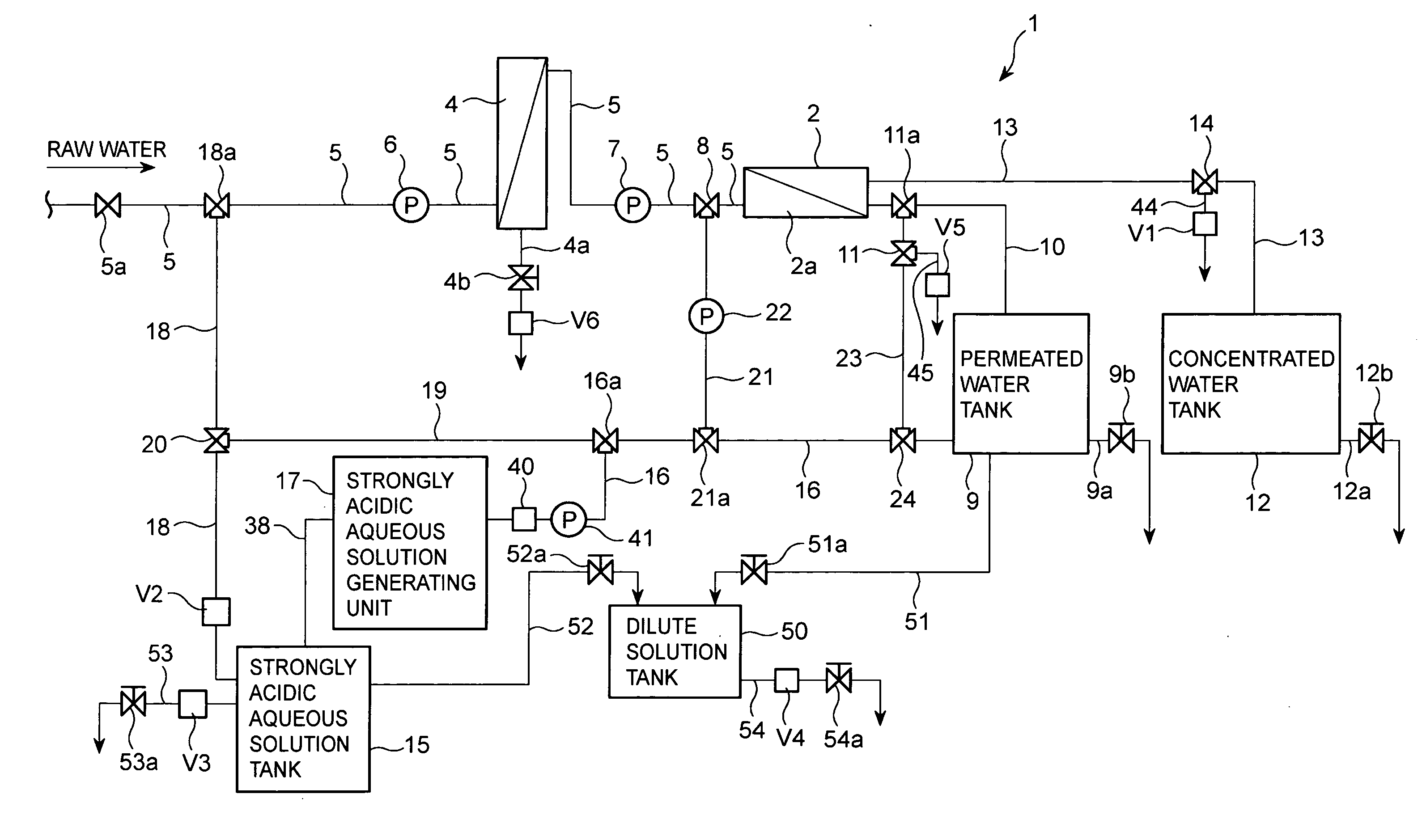
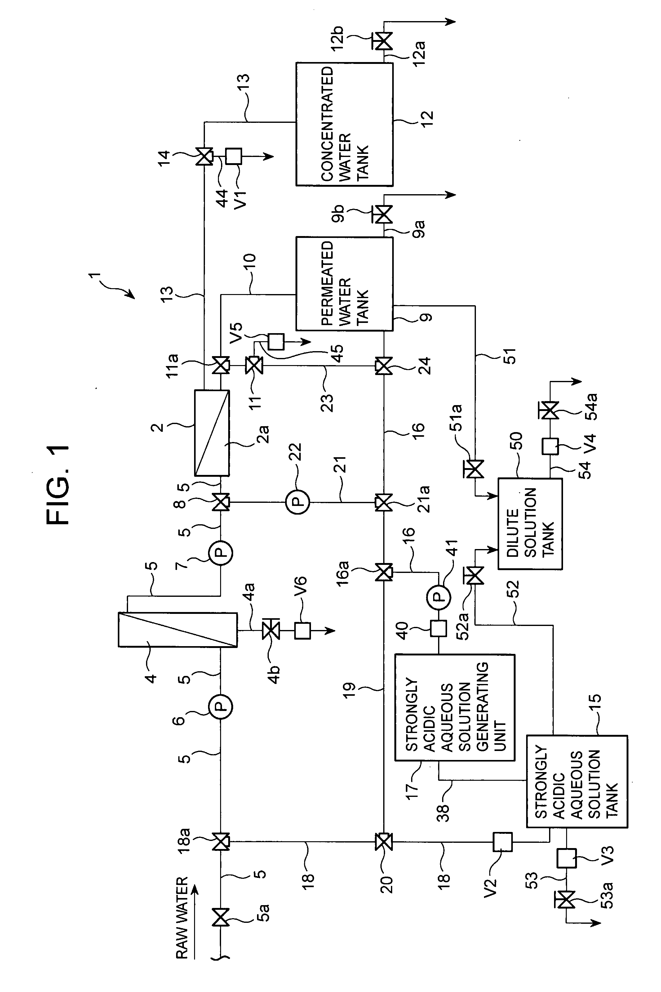
[0022]As shown in FIG. 1, a water treatment system 1 is provided with a reverse osmosis membrane module 2 as a filter, and a reverse osmosis membrane (not shown) is housed in a container body 2a of the reverse osmosis membrane module 2. The reverse osmosis membrane has a form of a hollow filament and a plurality of the membranes are stacked in a linear form or a U-shape and fixed by connecting with synthetic resin or the like at distal ends thereof. The reverse osmosis membrane used here is made of cellulose triacetate having acid resistance. The container body 2a has a sealed structure with an inlet and outlets (not shown) opened for feeding in raw water and for discharging permeated and concentrated water. To the inlet and outlets, a raw ...


PUM


Abstract

In a water treatment system with a function of filtering raw water, a filter can be securely and efficiently sterilized without using dangerous chemicals such as hydrochloric acid and sulfuric acid. The water treatment system 1 has a strongly acidic aqueous solution generating unit 17 provided with an electrolytic bath for storing a solution containing an electrolyte, the electrolytic bath having a cathode chamber and an anode chamber which are partitioned by an ion-permeable membrane, a cathode and an anode disposed in the cathode chamber and the anode chamber, respectively, and a voltage applying section for applying a direct current voltage between the cathode and the anode; a strongly acidic aqueous solution feeding passage 18 for connecting the strongly acidic aqueous solution generating unit 17 to a raw water inlet of a reverse osmosis membrane module 2 housing a reverse osmosis membrane to supply a strongly acidic aqueous solution generated in the strongly acidic aqueous solution generating unit 17 into the reverse osmosis membrane module 2; and potentiometers V1 and V5 for measuring a oxidation-reduction potential of the strongly acidic aqueous solution which has passed through the reverse osmosis membrane module 2.

Description

BACKGROUND OF THE INVENTION[0001]1. Field of the Invention[0002]The present invention relates to a water treatment system having a function for filtering various kinds of water such as seawater or river water.[0003]2. Description of the Related Art[0004]Techniques conventionally employed for seawater desalination, which belongs to water treatment technologies, are exemplified as a reverse osmosis method using a reverse osmosis membrane, a freeze concentration method for crystallizing water as ice, and an electrodialysis method to separate ions in a solution by an electric potential difference using a membrane having a fixed electric charge. Among these methods, the reverse osmosis method is widely known as the most efficient method for seawater desalination because the method, in particular, consumes the least energy. In a water treatment system using the reverse osmosis method, a reverse osmosis membrane module is provided, in which raw water is fed with pressure into the reverse o...

Claims


Application Information

Patent Timeline
IPC IPC(8): C02F1/44
CPCB01D61/025B01D61/04C02F2209/04C02F2103/08C02F2001/46185B01D61/58B01D65/022B01D65/08B01D2311/04B01D2321/162C02F1/441B01D2311/2688B01D2311/12Y02A20/131C02F1/4618C02F2201/4617
Inventor UKON, MASAYUKI
Owner HAKATAKO KANRI
Why Eureka
Try Eureka