Thermal head, method for manufacturing the same, and method for adjusting dot aspect ratio of thermal head

a technology of thermal head and dot, which is applied in the field of thermal head, can solve the problems of increasing yield and decreasing resistance value of the plurality of heating element parts, and achieve the effects of reducing resistance value variations, high image quality, and discharging hea

Inactive Publication Date: 2005-07-07
ALPS ALPINE CO LTD
View PDF3 Cites 69 Cited by
  • Summary
  • Abstract
  • Description
  • Claims
  • Application Information

AI Technical Summary

Benefits of technology

[0006] It is an object of the present invention to provide a thermal head in which variations in dot resistance value are reduced, a desired dot aspect ratio can be attained without using any heating element portion having a high resistivity and, thereby, high-quality printing can be realized, a method for manufacturing the same, and a method for adjusting a dot aspect ratio of a thermal head.
[0007] The present invention is based on findings that when the two-dimensional sizes of a plurality of heating element portions are specified to be rectangular (aspect ratio >>1) by insulating barrier layers, the plurality of heating element portions can be readily produced and variations in dot resistance value are reduced and that the dot aspect ratio can be readily adjusted by regulating effective heating regions of the plural heating element portions.
[0010] Preferably, the two-dimensional shape of the effective heating region of the heating element portion is specified to be square by the heat transfer layer. When the two-dimensional shape of the effective heating region of the heating element portion is square, one printing dot becomes a square pixel and, therefore, the printing quality is improved.
[0011] Preferably, the two-dimensional shape of each heating element portion specified by the insulating barrier layer is rectangular. When the two-dimensional shape of the heating element portion is rectangular, that is, when the aspect ratio of the heating element portion is larger than 1, variations in amount of etching can be reduced in the step of forming the plurality of heating element portions compared with that in the case where the two-dimensional shape of the heating element portion is specified to be square. Consequently, variations in dot resistance value are also reduced. Furthermore, the dot resistance value can be ensured even when the heating element portion is not formed from a resistance material having a high resistivity. The two-dimensional shape of the effective heating region of each heating element portion can be readily specified to be square by the above-described heat transfer layer even when the two-dimensional shape of each heating element portion is rectangular.
[0015] According to the present invention, since the heat transfer layer is provided to determine the two-dimensional surface exposure area of the insulating barrier layer by covering part of the insulating barrier layer and to dissipate the heat generated from the plurality of heating element portions, and the surface exposure regions of the insulating barrier layer are specified as effective heating regions of the plural heating element portions by the heat transfer layer, the effective heating regions and the dot aspect ratios of the plurality of heating element portions can readily be changed by adjusting the two-dimensional sizes of the heat transfer layers (spacing between them, length dimension, and width dimension). In particular, when the two-dimensional sizes of the plurality of heating element portions are specified to be rectangular (aspect ratio >>1) by insulating barrier layers and the dot aspect ratios of the plurality of heating element portions are substantially specified to be 1 by the heat transfer layers, one printing dot can be made a square pixel while variations in dot resistance value are reduced. Consequently, high image quality can be attained when the direction of the printing is either a vertical direction or a horizontal direction and, therefore, high-quality printing can be realized.

Problems solved by technology

However, when the dot aspect ratio L / W is brought close to 1, the amount of etching tends to vary in a photolithography step to form a plurality of heating element portions, and there is a problem in that variations in resistance value (dot resistance value) of the plurality of heating element portions are increased.
If variations in dot resistance value exceed a specific level, no product of satisfactory quality is attained and, therefore, the yield is decreased.

Method used


Image

  • Thermal head, method for manufacturing the same, and method for adjusting dot aspect ratio of thermal head
  • Thermal head, method for manufacturing the same, and method for adjusting dot aspect ratio of thermal head
  • Thermal head, method for manufacturing the same, and method for adjusting dot aspect ratio of thermal head

Examples


first embodiment

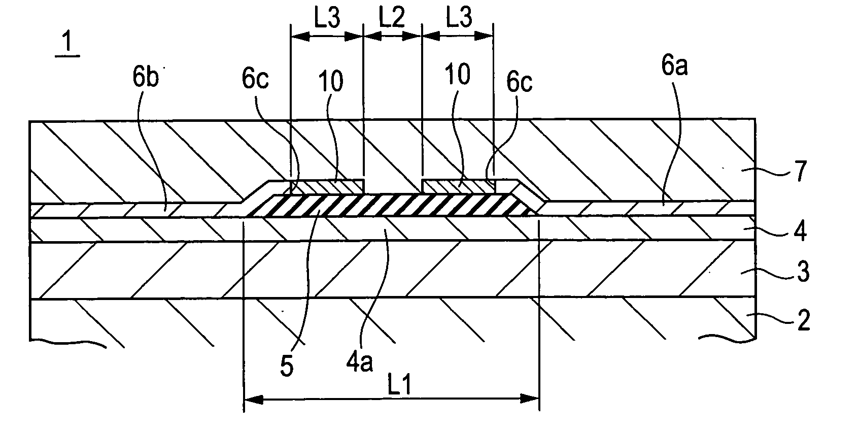
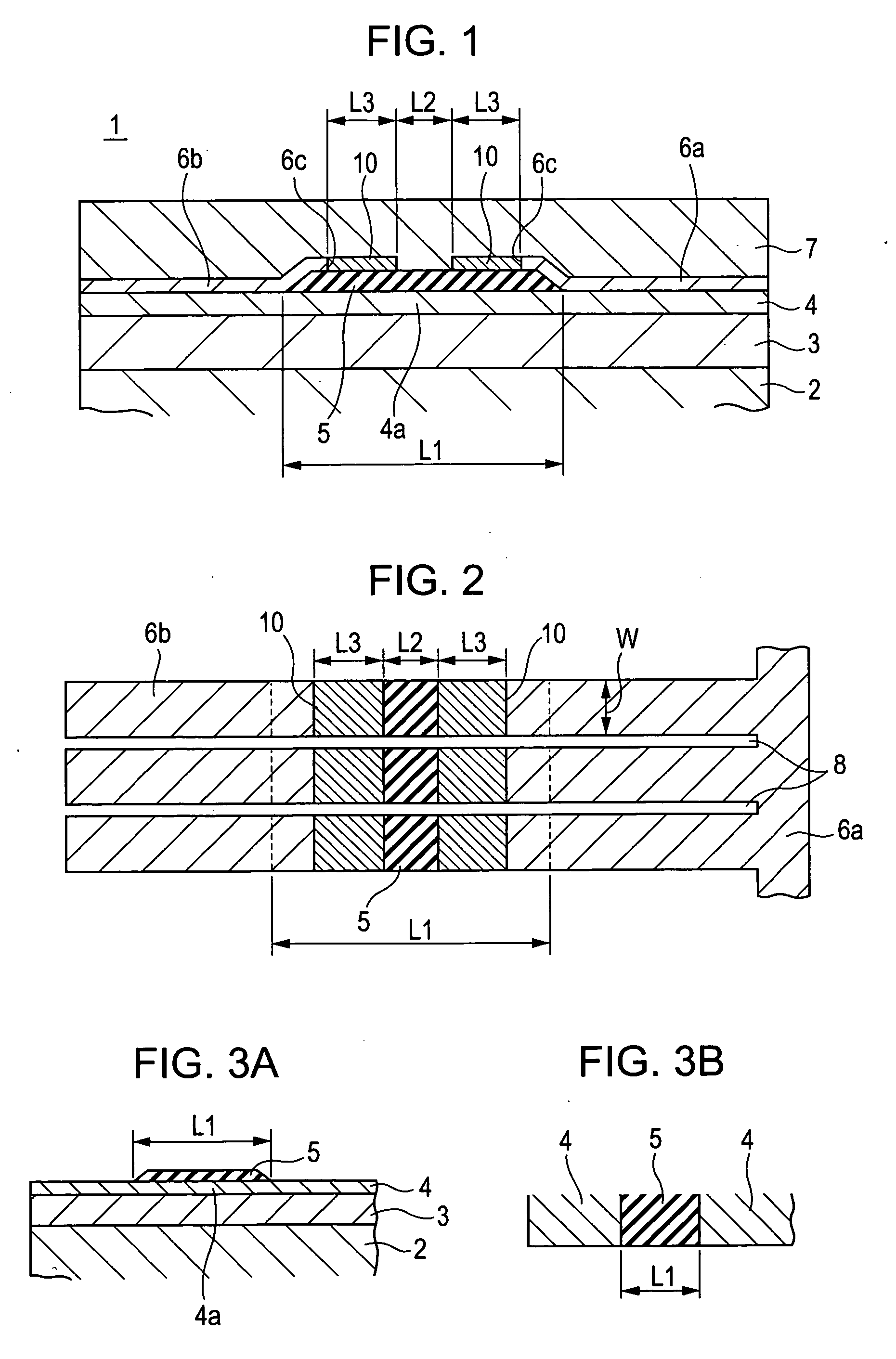
[0028]FIG. 1 and FIG. 2 are a sectional view and a plan view (except an abrasion-resistant protective layer), respectively, showing a thermal head according to the present invention. The present thermal head 1 is provided with a plurality of heating element portions 4a which generate heat by energization, an insulating barrier layer 5 covering the surface of each heating element portion 4a, electrode layers 6 electrically connected to two end portions of each of the plural heating element portions 4a in the length direction of the resistance, and an abrasion-resistant protective layer 7 on a heat dissipating substrate 2 including a heat storage layer 3. This thermal head 1 is mounted on a photo printer or a thermal printer, and performs printing by applying heat generated from each heating element portion 4a to thermal paper or an ink ribbon. Although not shown in the drawing, the thermal head 1 is also provided with a driving IC, a printed circuit board, and the like to control ene...

second embodiment

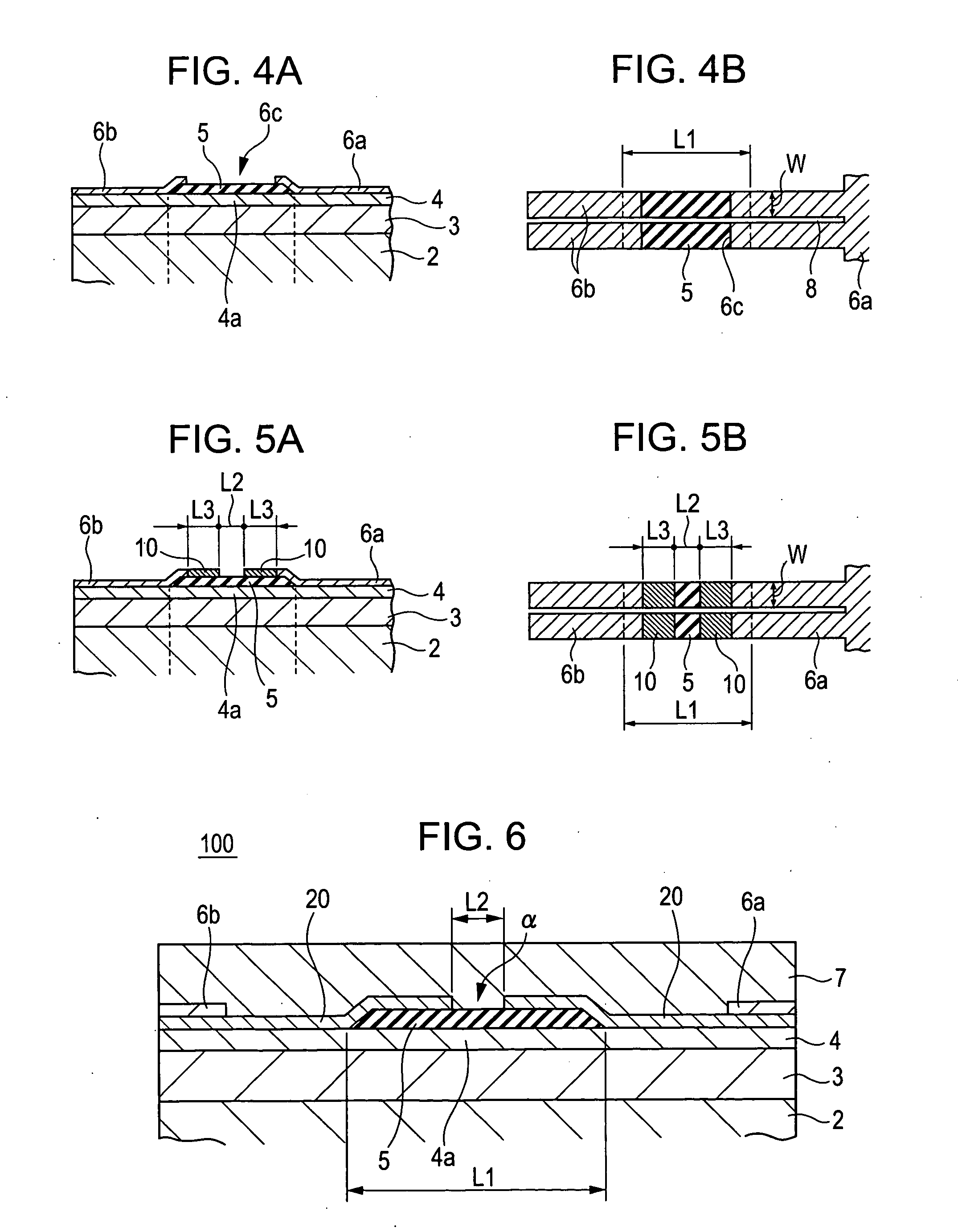
[0046] According to this second embodiment as well, the effective heating regions of the plurality of heating element portions 4a are determined by the heat transfer layers 20, the effective heating regions and the dot aspect ratios (L2 / W) of the plurality of heating element portions 4a can readily be changed by adjusting the two-dimensional sizes of the heat transfer layers 20 (spacing L2 between them, length dimension L3, and width dimension).

[0047]FIG. 10 and FIG. 11 are exothermic distribution diagrams showing the head surface temperatures when heating element portions 4a are in the energized condition in a known type thermal head provided with no heat transfer layer and the thermal head 1 provided with the heat transfer layers according to the present first embodiment, respectively. In FIG. 10 and FIG. 11, dot portions of the known type thermal head and the present thermal head 1 are enclosed with broken lines. As shown in FIG. 12, the two-dimensional size (length dimension L1 ...


PUM


Abstract

In a thermal head provided with a resistance layer having a plurality of heating element portions which generate heat by energization, an insulating barrier layer which determines the two-dimensional size of each heating element portion by covering each heating element portion, and electrode layers electrically connected to two end portions of each of the plural heating element portions, in the length direction of the resistance, a heat transfer layer is disposed on at least the insulating barrier layer to determine the two-dimensional surface exposure area of the insulating barrier layer by covering part of the insulating barrier layer and to dissipate the heat generated from the plural heating element portions, and surface exposure regions of the insulating barrier layer are specified as effective heating regions of the plural heating element portions by adjusting the two-dimensional size of the heat transfer layer.

Description

BACKGROUND OF THE INVENTION [0001] 1. Field of the Invention [0002] The present invention relates to a thermal head mounted on a thermal printer and the like, a method for manufacturing the same, and a method for adjusting a dot aspect ratio of a thermal head. [0003] 2. Description of the Related Art [0004] In general, a thermal head includes a plurality of heating element portions which generate heat by energization, electrode layers to energize the plurality of heating element portions, and a protective layer to protect the plurality of heating element portions and part of the electrode layers, on a heat dissipating substrate provided with a heat storage layer. The heating element portion generating heat is pressed against an ink ribbon and a printing substrate wound around a platen roller and, thereby, the printing operation is performed. In such a known thermal head, each heating element portion to produce one printing dot is formed into the shape of a rectangle. But, it is desi...

Claims


Application Information

Patent Timeline
Patent Type & Authority Applications(United States)
IPC IPC(8): B41J2/345B41J2/335
CPCB41J2/3353B41J2/33515
Inventor NAKATANI, TOSHIFUMIUSAMI, SHUUICHITERAO, HIROTOSHI
Owner ALPS ALPINE CO LTD
Why Eureka
Try Eureka