Fiber tip based sensor system for measurements of pressure gradient, air particle velocity and acoustic intensity

a technology of air particle velocity and sensor system, applied in the field of measurement system, can solve the problems of limiting the application of this type of sensor, limiting the control of sound transmission into enclosed spaces, and no commercially available fiber optic sensor system which may be used for these measurements

Inactive Publication Date: 2005-07-07
MARYLAND UNIV OF
View PDF18 Cites 54 Cited by
  • Summary
  • Abstract
  • Description
  • Claims
  • Application Information

AI Technical Summary

Problems solved by technology

For example, in helicopter systems, control of sound transmission into enclosed spaces is an important issue.
However, the sensor bandwidth was found to be limited, and in addition, the sensor was found to have low sensitivity due to the high Young's modules of silica resulting in “acoustically induced strains” which also limit the application of this type of sensors.
Currently, there are no commercially available fiber optic sensor systems which may be used for these measurements since the current technology is primarily based on condenser microphones.
However, complexity and bulkiness of known velocity microphones makes them difficult to use effectively in ASAC systems.
Although the size of the sensor was “small” compared to many commercially available velocity probes, it was shown that such a sensor could lead to errors if there is any mismatching between the different pressure microphones.
There may also be the potential for interference, since a plurality of microphones are generally housed together in a small volume.
This interference may significantly affect the sensor signal-to-noise ratio, especially at low sound pressure levels.
However, these sensors are dependent on thermal effects, and therefore, operate at very high temperatures.

Method used


Image

  • Fiber tip based sensor system for measurements of pressure gradient, air particle velocity and acoustic intensity
  • Fiber tip based sensor system for measurements of pressure gradient, air particle velocity and acoustic intensity
  • Fiber tip based sensor system for measurements of pressure gradient, air particle velocity and acoustic intensity

Examples


Embodiment Construction

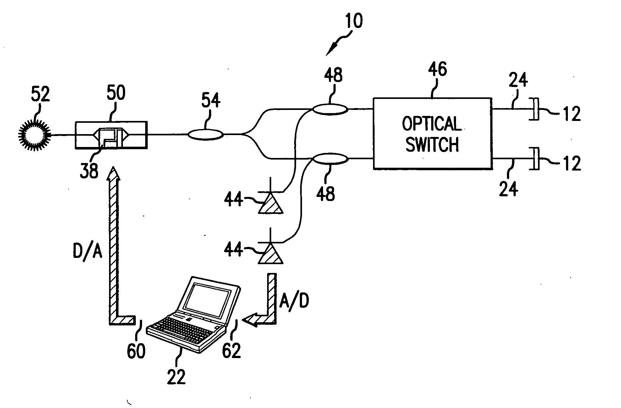
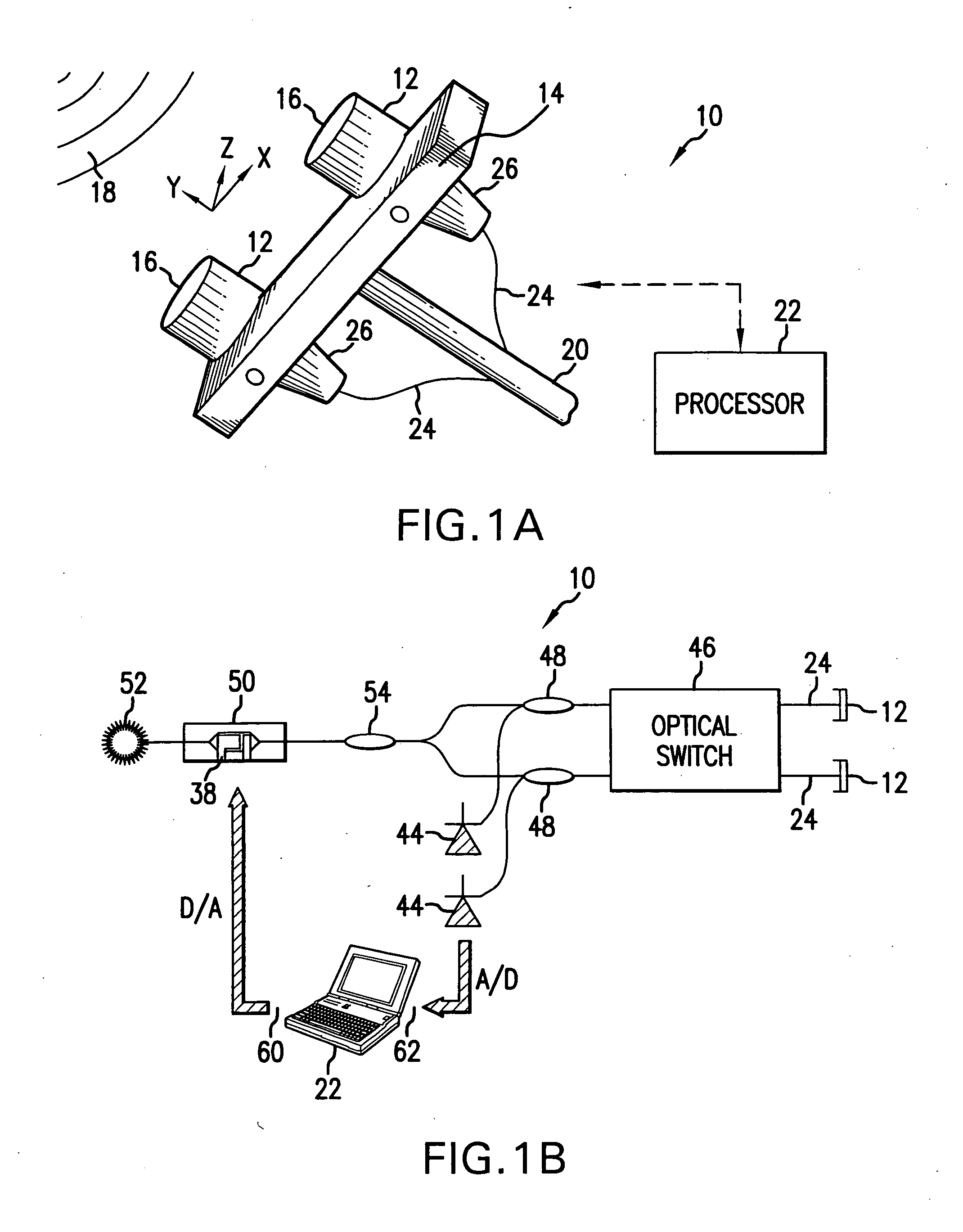
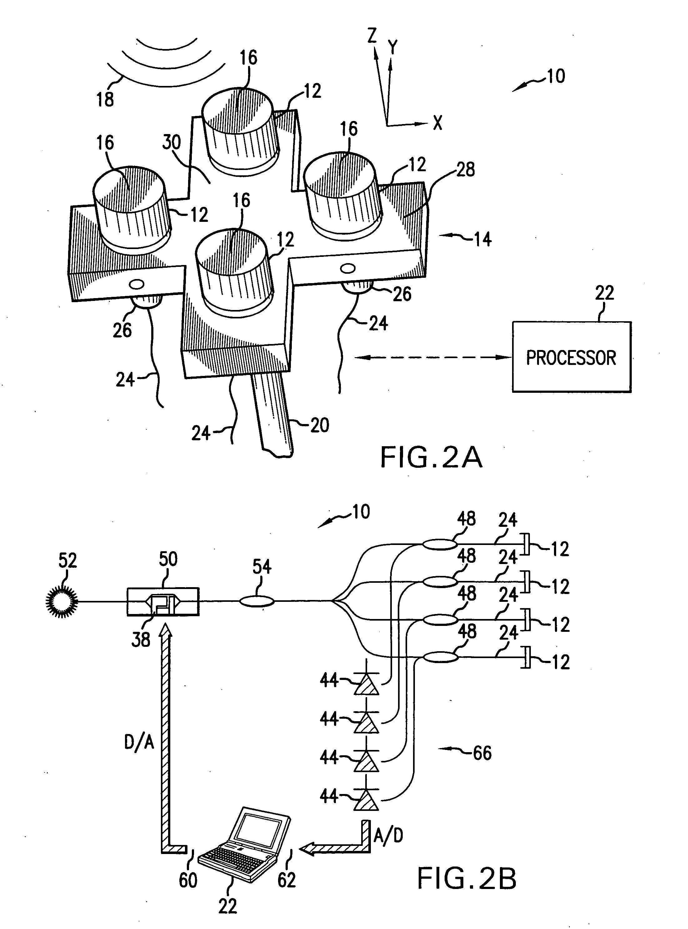
[0059] In FIGS. 1A, 2A, and 3A, as well as FIGS. 1B, 2B, and 3B, the one-dimensional, two-dimensional, and three-dimensional pressure gradient sensor system of the present invention are shown, respectively. System 10 includes a pair of sensors 12 for one-dimensional measurements, two pairs of sensors 12 for two-dimensional measurements, and three pairs of sensors 12 for three-dimensional measurements of acoustic parameters, such as pressure gradient, air particle velocity, and acoustic intensity of an acoustic disturbance.

[0060] Referring particularly to FIG. 1A, a 1-D spatial sensor includes a supporting member 14 to which a pair of Fabry-Perot sensors 12 are attached at a predetermined distance l one from the other. These sensors 12 are aligned along a single axis, shown as the axis Y in FIG. 1A, and are directed with their front surfaces 16 facing an acoustic field 18 which is to be sensed. The supporting member 14 may be manipulated by a directing member 20 that is controlled e...


PUM


Abstract

A fiber optic sensor system for pressure measurements where the design permits multiplexity on the input side of the system and the optical part of the system, which has a sensor Fabry-Perot interferometer and a read-out interferometer, is based on low coherence fiber-optic interferometry techniques. This permits a high dynamic range and low sensitivity to the wavelength fluctuation of the light source as well as to the optical intensity fluctuations. The system includes fiber tip based Fabry-Perot sensors, where each sensor includes a diaphragm as the transducer. A combined pressure gradient sensor, air particle velocity sensor, as well as acoustic intensity sensor is built based on the fiber tip based Fabry-Perot sensors.

Description

REFERENCE TO RELATED APPLICATIONS [0001] This Utility Patent Application is based on a Provisional Patent Application No. 60 / 569,297 filed May 7, 2004, and is a Continuation-in-Part of the Utility Patent Application Serial #10 / 270,277 filed Oct. 15, 2002.FIELD OF THE INVENTION [0002] The present invention relates to measurement systems, and in particular to fiber tip based optic sensor systems for active acoustics and vibration control, permitting measurements of various acoustic parameters. [0003] More in particular, the present invention relates to fiber tip based low-finesse Fabry-Perot sensor system for pressure gradient, air particle velocity and acoustic intensity measurements. BACKGROUND OF THE INVENTION [0004] In the design of modern transportation vehicles, structural vibration and interior noise have become important problem areas that must be addressed. For example, in helicopter systems, control of sound transmission into enclosed spaces is an important issue. Various st...

Claims


Application Information

Patent Timeline
Patent Type & Authority Applications(United States)
IPC IPC(8): G01D5/353G01H9/00G02B6/34
CPCG01D5/35303G02B6/29358G01H9/006
Inventor BALACHANDRAN, BALAKUMARAL-BASSYIOUNI, MOUSTAFAYU, MIAO
Owner MARYLAND UNIV OF
Why Eureka
Try Eureka