Ofdm demodulation apparatus

Inactive Publication Date: 2005-07-07
SONY CORP
View PDF5 Cites 99 Cited by
  • Summary
  • Abstract
  • Description
  • Claims
  • Application Information

AI Technical Summary

Benefits of technology

[0046] Accordingly, the present invention has an object to overcome the above-mentioned drawbacks of the related art by providing a

Problems solved by technology

The long control pass ne

Method used


Image

  • Ofdm demodulation apparatus
  • Ofdm demodulation apparatus
  • Ofdm demodulation apparatus

Examples


first embodiment

[0109] The present invention will be described in detail below concerning the OFDM receiver as the first embodiment thereof.

[0110] Overview of the OFDM Receiver

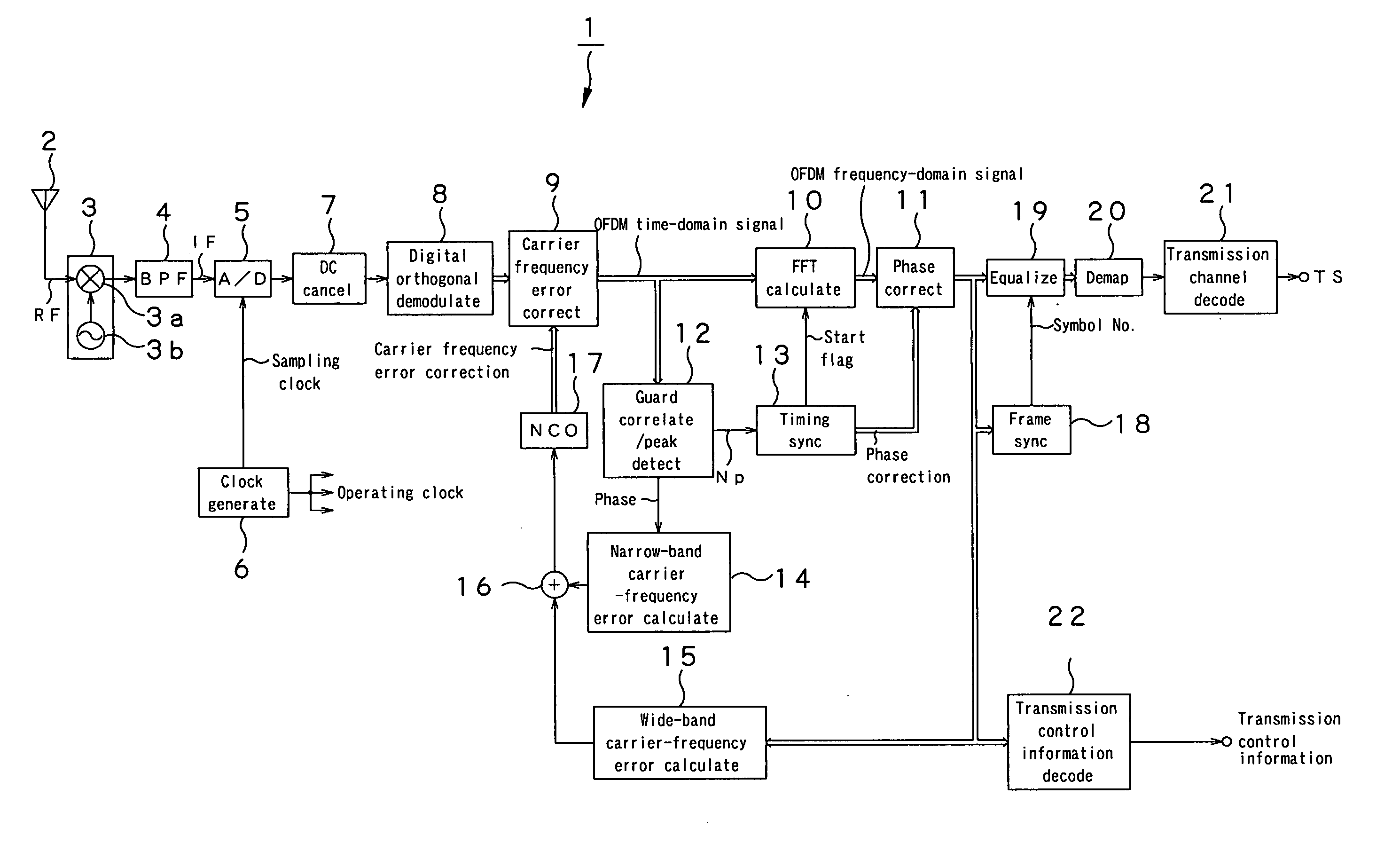
[0111]FIG. 6 is a block diagram of the OFDM receiver according to the first embodiment of the present invention.

[0112] As show in FIG. 6, the OFDM receiver, generally indicated with a reference 1, as the first embodiment of the present invention includes an antenna 2, tuner 3, band-pass filter (BPF) 4, A-D conversion circuit 5, clock generation circuit 6, DC canceling circuit 7, digital orthogonal demodulation circuit 8, carrier-frequency error correction circuit 9, FFT calculation circuit 10, phase correction circuit 11, guard correlation / peak detection circuit 12, timing synchronization circuit 13, narrow-band carrier error calculation circuit 14, wide-band carrier error calculation circuit 15, addition circuit 16, numerical-control oscillation (NCO) circuit 17, frame synchronization circuit 18, equalization circuit 19, ...

second embodiment

[0331] Next, the second embodiment of the present invention will be illustrated and described.

[0332] The OFDM receiver as the second embodiment of the present invention is designed similarly to the OFDM receiver 1 according to the aforementioned first embodiment except for a symbol-boundary calculation circuit that is a modified version of the symbol-boundary calculation circuit 43. Therefore, the OFDM receiver according to the second embodiment will be illustrated and described concerning only the symbol-boundary calculation circuit. The same or similar components as or to those in the first embodiment will be indicated with the same or similar references as or to those used in the drawings to which reference has been made in the description of the first embodiment, and will not be described in detail any more.

[0333]FIG. 35 is a block diagram of the symbol-boundary calculation circuit provided in the OFDM receiver as the second embodiment. The symbol-boundary calculation circuit ...

third embodiment

[0346] Next, the third embodiment of the present invention will be illustrated and described.

[0347] The OFDM receiver as the third embodiment of the present invention is similar to the OFDM receiver 1 as the first embodiment except for a guard correlation / peak detection circuit and symbol-boundary calculation circuit which are modified versions of the guard correlation / peak detection circuit 12 and symbol-boundary calculation circuit 43, respectively, in the first embodiment. Therefore, the OFDM receiver according to the third embodiment will be described concerning only the guard correlation / peak detection circuit and symbol-boundary calculation circuit. The same or similar components as or to those in the first embodiment will be indicated with the same or similar references as or to those used in the drawings to which reference has been made in the description of the first embodiment, and will not be described in detail any more.

[0348]FIG. 37 is a block diagram of the guard cor...


PUM


Abstract

An OFDM demodulation (1) is provided which includes a guard correlation/peak time detection circuit (12) to generate a peak timing Np of a guard interval correlation value, and a timing synchronization circuit (13) to estimate a symbol-boundary time Nx from the peak timing Np. The timing synchronization circuit (13) calculates the symbol-boundary time Nx by filtering the peak time Np by a DLL (delay locked loop) filter (43). Further, the DLL filter (43) includes a limiter (52) to limit the range of phase-error component and an asymmetric gain circuit (53) to change the magnitude of the gain correspondingly to the polarity of the phase error to prevent the timing from being pulled out due to a fading or multipath.

Description

TECHNICAL FIELD [0001] The present invention relates to a demodulator destined for demodulation of an OFDM (orthogonal frequency division multiplex) modulated signal. [0002] This application claims the priority of the Japanese Patent Application No. 2002-382212 filed on Dec. 27, 2002, the entirety of which is incorporated by reference herein. BACKGROUND ART [0003] For transmission of digital signals, there is available a modulation technique called “OFDM” (orthogonal frequency division multiplex). The OFDM technique is such that data is digitally modulated for transmission by dividing a transmission frequency band into many orthogonal sub-carriers and assigning the data to the amplitude and phase of each of the sub-carriers by the phase shift keying (PSK) and quadrature amplitude modulation (QAM). [0004] The OFDM technique is characterized in that since a transmission frequency band is divided into many sub-carriers, so the band per sub-carrier is narrower and the modulation rate is...

Claims


Application Information

Patent Timeline
IPC IPC(8): H04J11/00H04L7/08H04L27/14H04L27/26
CPCH04L27/2605H04L27/2676H04L27/2657H04L27/2662
Inventor FUNAMOTO, KAZUHISAOKADA, TAKAHIROIKEDA, TAMOTSUYAJIMA, ATSUSHIIKEDA, YASUNARI
Owner SONY CORP
Why Eureka
Try Eureka