Layered barrier structure having one or more definable layers and method

a barrier structure and layer technology, applied in the direction of cell components, flat cell grouping, sustainable manufacturing/processing, etc., can solve the problems of not being able to integrate into small packages, power supply that is quite heavy or large, and power supply that cannot be quite heavy or large compared to current batteries, etc., to achieve sufficient energy storage, reduce gas transmission, and reduce corrosion and other deleterious reactions

Inactive Publication Date: 2005-07-07
CYMBET CORP
View PDF99 Cites 151 Cited by
  • Summary
  • Abstract
  • Description
  • Claims
  • Application Information

AI Technical Summary

Benefits of technology

[0013] In some embodiments, layered structures are utilized, including a plurality of deposited pairs of layers, each pair including a physical configuration layer and a barrier layer with low gas-transmission rates (e.g., less than 0.1 ml gas per square meter per day). In some embodiments, such layered structures having several pairs of layers are effective in reducing gas transmission to levels effective in reducing corrosion and other deleterious reactions with the materials in batteries or other sealed components (i.e., to levels below the detection limits of transmission-rat

Problems solved by technology

One drawback to portable devices is the need to include the power supply with the device.
Sufficient battery capacity can result in a power supply that is quite heavy or large compared to the rest of the device.
In other words, current batteries generally are rather large and cannot be incorporated into small packages.
Most batteries today are fairly e

Method used


Image

  • Layered barrier structure having one or more definable layers and method
  • Layered barrier structure having one or more definable layers and method
  • Layered barrier structure having one or more definable layers and method

Examples


Embodiment Construction

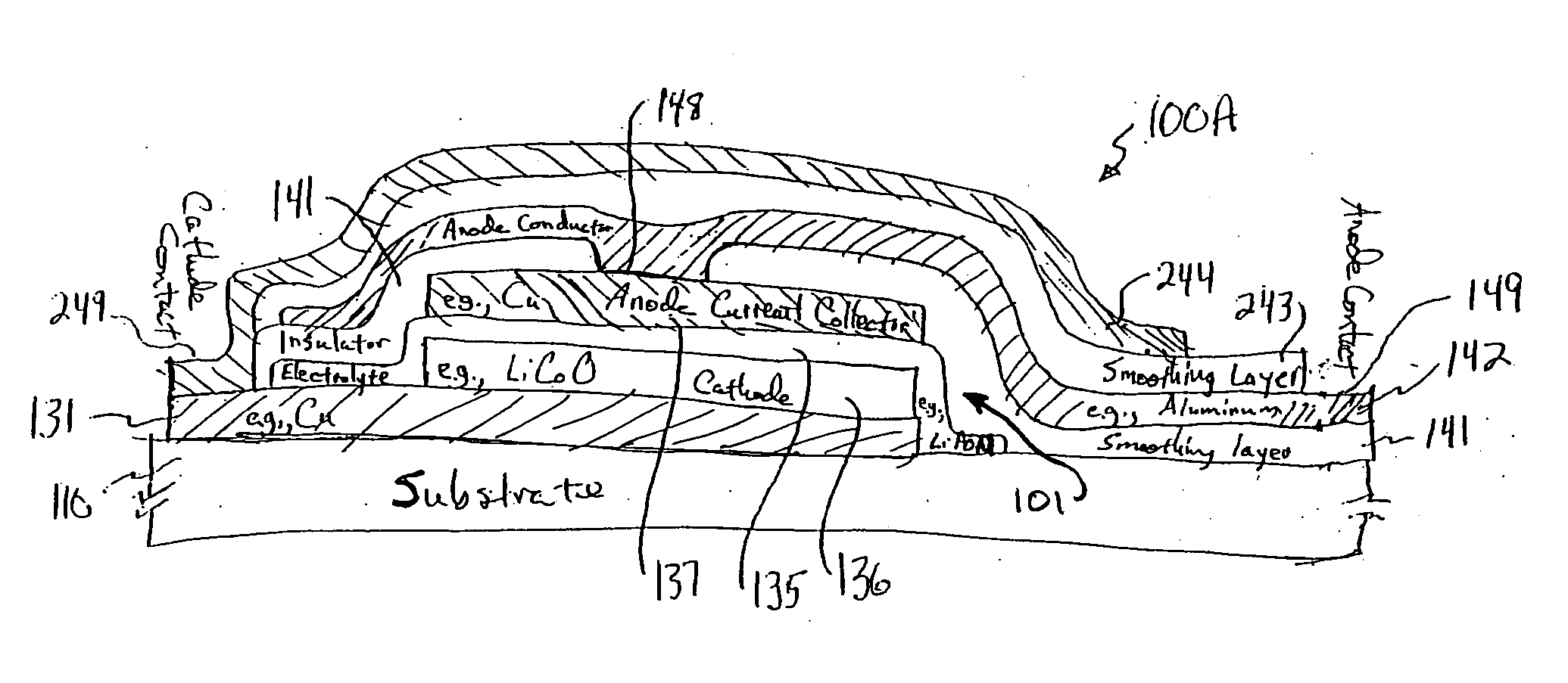
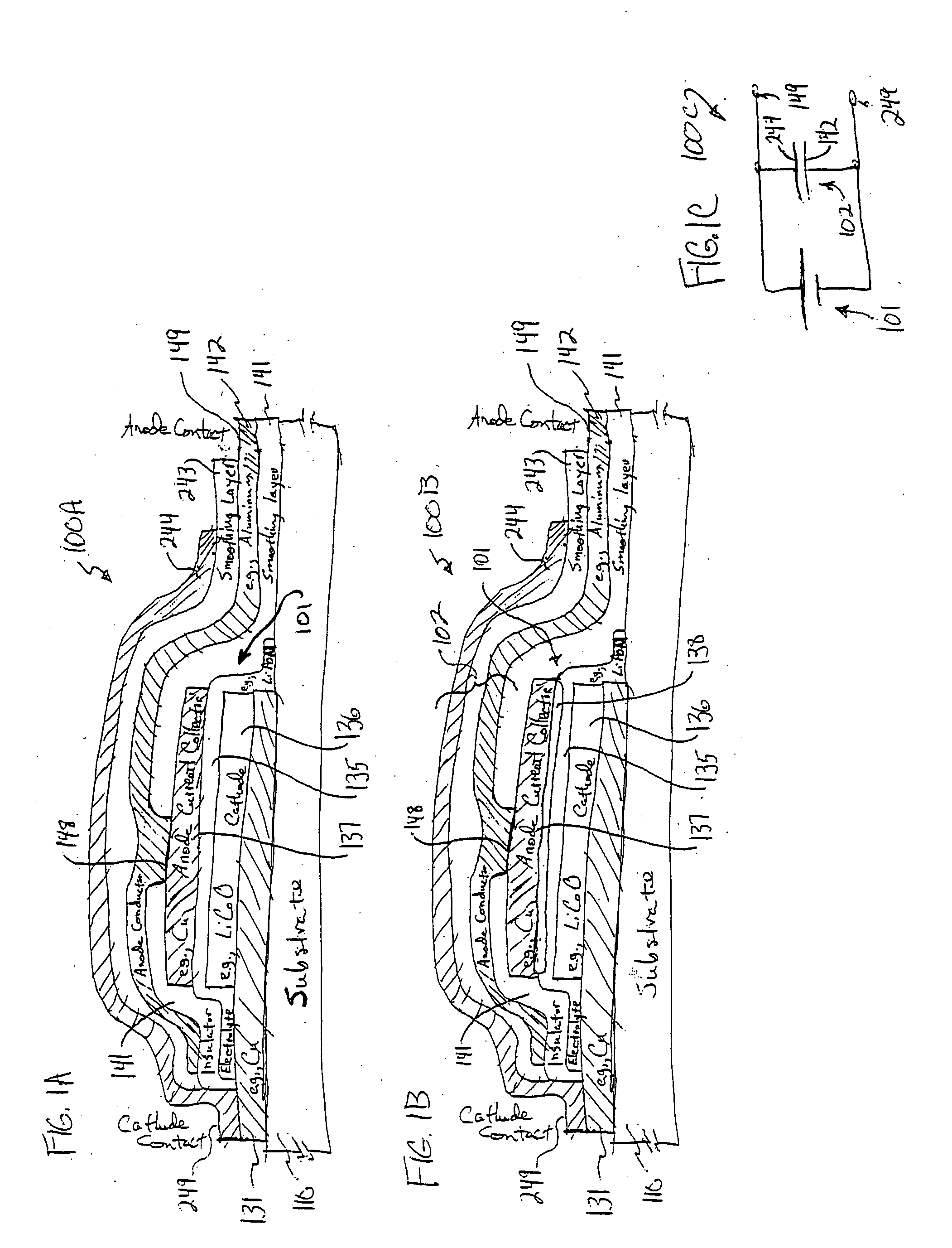
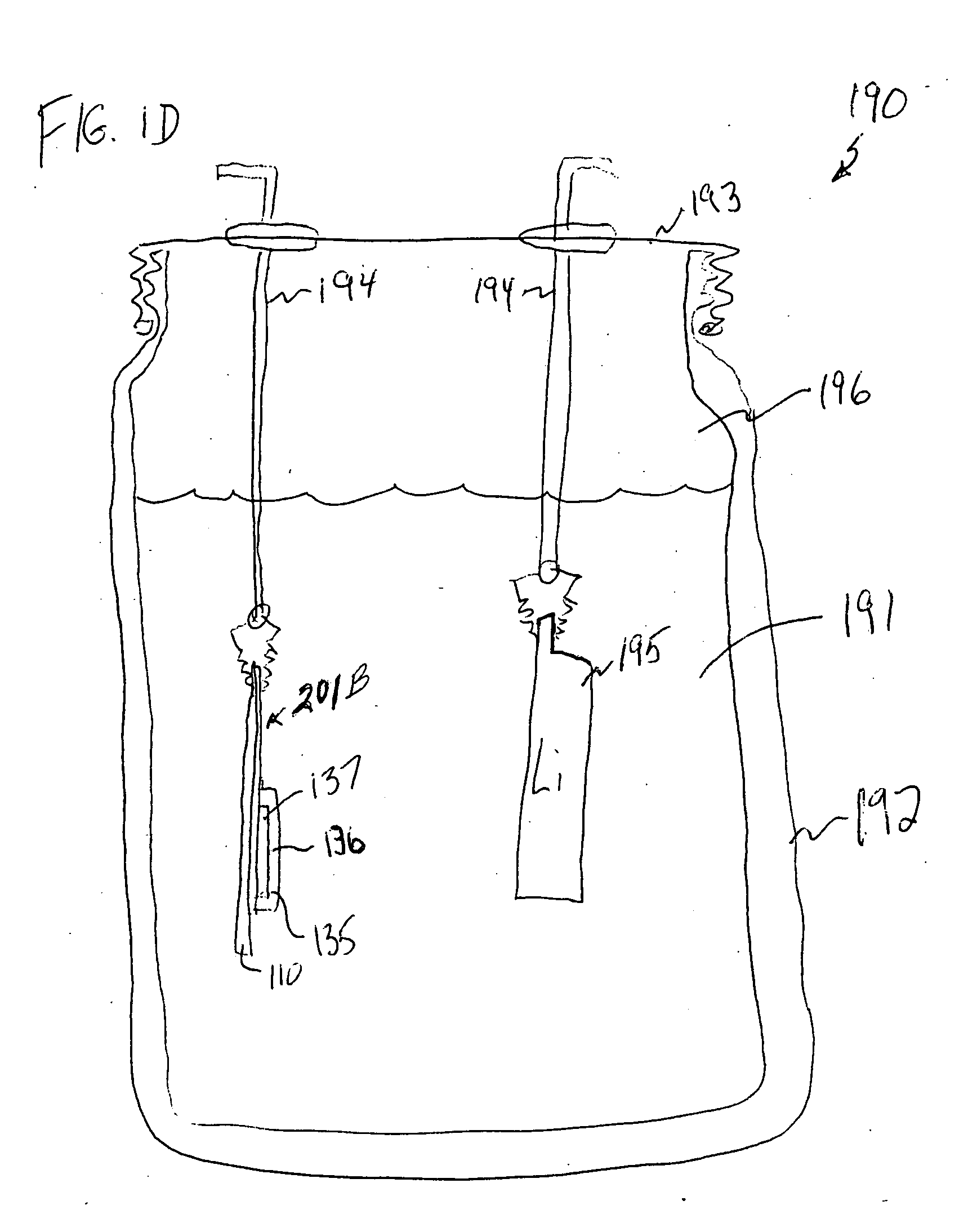
[0058] In the following detailed description of preferred embodiments, reference is made to the accompanying drawings that form a part hereof, and in which are shown, by way of illustration, specific embodiments in which the invention may be practiced. It is to be understood that other embodiments may be utilized and structural changes may be made without departing from the scope of the present invention.

[0059] It is to be understood that in different embodiments of the invention, each battery in the Figures or the description can be implemented using one or more cells, and if a plurality of cells is implemented, the cells can be wired in parallel or in series. Thus, where a battery or more than one cell is shown or described, other embodiments use a single cell, and where a single cell is shown or described, other embodiments use a battery or more than one cell. Further, the references to relative terms such as top, bottom, upper, lower, etc. refer to an example orientation such a...


PUM


Abstract

A system provides an environmental barrier also useful for providing a circuit, for example, one having a thin-film battery such as one that includes lithium or lithium compounds connected to an electronic circuit. An environmental barrier is deposited as alternating layers, at least one of the layers providing a smoothing, planarizing, and/or leveling physical-configuration function, and at least one other layer providing a diffusion-barrier function. The layer providing the physical-configuration function may include a photoresist, a photodefinable, an energy-definable, and/or a maskable layer. The physical-configuration layer may also be a dielectric. A layered structure, including a plurality of pairs of layers, each pair including a physical configuration layer and a barrier layer with low gas-transmission rates, may be used in reducing gas transmission rate to beyond currently detectable levels.

Description

CROSS-REFERENCES TO RELATED INVENTIONS [0001] This invention is related to U.S. Pat. No. 6,805,998 entitled “METHOD AND APPARATUS FOR INTEGRATED-BATTERY DEVICES,” U.S. patent application Ser. No. 09 / 815,884 (Attorney Docket No. 1327.011 US1) entitled “Battery-Operated Wireless-Communication Apparatus and Method,” filed Mar. 23, 2001, and U.S. patent application Ser. No. 10 / 336,662 (Attorney Docket No. 1327.018US1) entitled “Active Wireless Tagging System On Peel And Stick Substrate,” filed Jan. 2, 2003; each of which is incorporated by reference. [0002] This claims benefit of U.S. Provisional Patent Application Ser. No. 60 / 534,660, filed Jan. 6, 2004 by David J. Tarnowski and Mark L. Jenson.FIELD OF THE INVENTION [0003] The present invention relates to solid-state energy-storage devices and integration of these devices with packaged circuits. More particularly, this invention relates to methods and systems for providing an environmental barrier to various apparatus, for example, tho...

Claims


Application Information

Patent Timeline
IPC IPC(8): B05D5/12H01M4/02H01M4/04H01M10/052H01M50/11H01M50/119H01M50/121H01M50/124H01M50/186H01M50/191H01M50/193H01M50/197H01M50/198
CPCH01M2/0207Y02E60/124H01M2/0275H01M2/08H01M4/02H01M4/04H01M4/244H01M6/40H01M10/052H01M10/4242H01M10/44H01M12/06H01M2300/0014Y02E60/122H01M2/0267H01L2224/18Y02E60/10Y02P70/50H01M50/121H01M50/186H01M50/11H01M50/193H01M50/124H01M50/198H01M50/191H01M50/197H01M50/119
Inventor TARNOWSKI, DAVE J.JENSON, MARK L.
Owner CYMBET CORP
Why Eureka
Try Eureka