System and method of designing and manufacturing customized instrumentation for accurate implantation of prosthesis by utilizing computed tomography data

a computed tomography and customized instrument technology, applied in the field of customized instruments, can solve the problems of acetabular cup not fully sitting in the reamed cavity of the acetabulum, surgeons may have difficulty in reaming a properly sized cavity, and the sub-hemispherical configuration suffers from a number of limitations, so as to achieve quick and accurate implantation of the guide, easy oriented, and quick fabrication

Active Publication Date: 2005-07-07
DEPUY PROD INC
View PDF37 Cites 525 Cited by
  • Summary
  • Abstract
  • Description
  • Claims
  • Application Information

AI Technical Summary

Benefits of technology

[0021] One advantage of the present invention is that a surgical guide may be designed and manufactured in a way that quickly and accurately attaches the guide at the surgical site so a prosthetic component may be easily oriented at the joint for optimal placement.
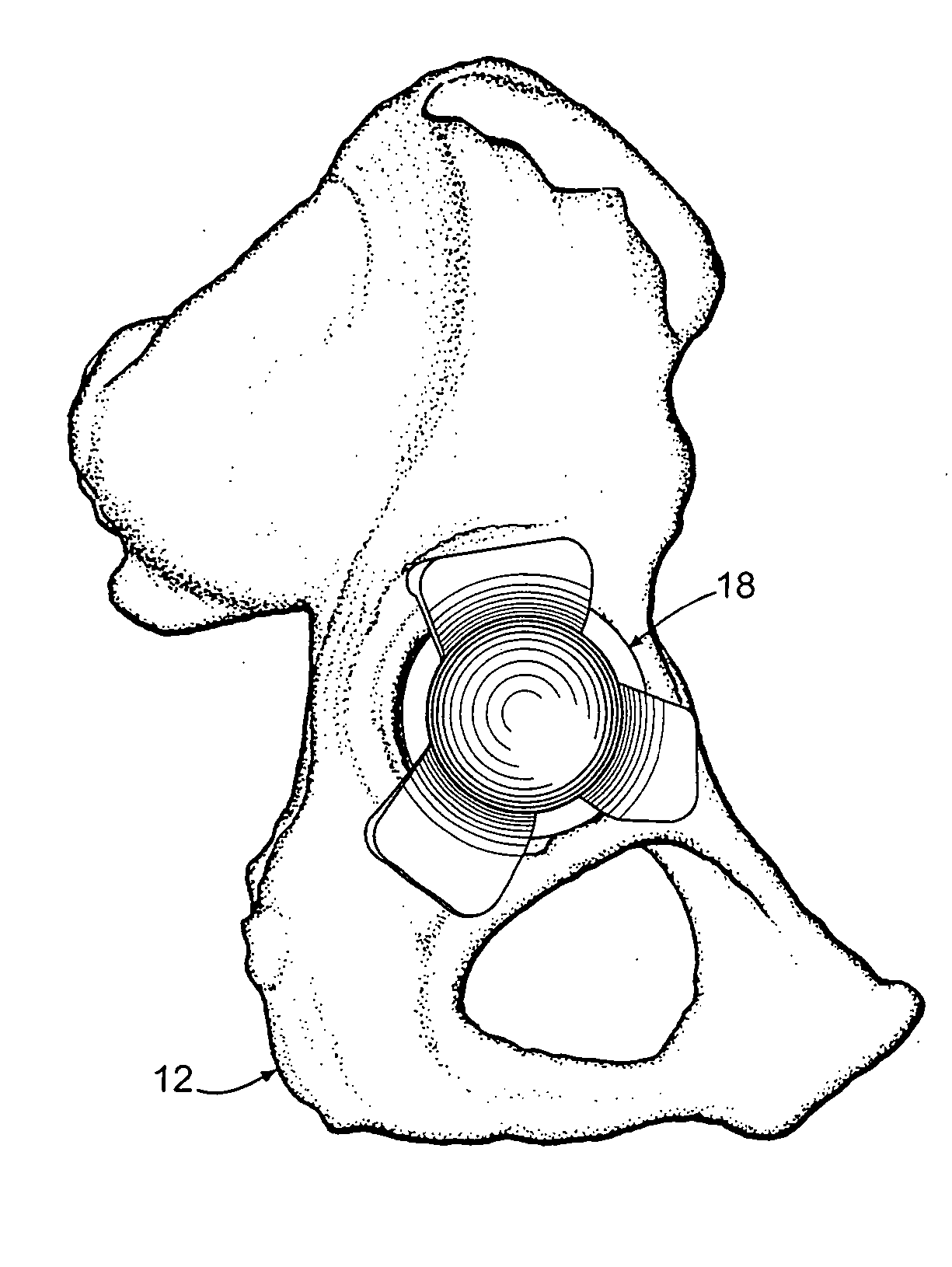
[0022] Another advantage of the present invention is that a surgical guide may be designed and manufactured to conform to the bony structure surrounding a cavity for receiving an acetabular cup so the cup is properly oriented with respect to the reconstructed acetabulum of the innominate bone.
[0023] Another advantage of the present invention is that a surgical guide may be designed and manufactured so the supporting structure of the guide does not...

Problems solved by technology

One problem that surgeons encounter is being able to properly match the size of the reamer to the desired acetabular cup size.
A sub-hemispherical configuration suffers from a number of limitations.
For example, a surgeon may have difficulty in reaming a properly sized cavity for an acetabular cup that is not truly hemispherical.
This difficulty arises because the cutting heads of reamers are typically configured as relatively true hemispheres.
Conversely, if the surgeon reams too shallowly (i.e. “under reams”), the acetabular cup does not fully seat in the reamed cavity of the acetabulum.
Because a surgeon may occasionally select a reamer that is slightly smaller than the acetabular cup to be implanted, under reaming may also disadvantageously lead to bone fracture of the acetabulum since excessive force may be used to insert the cup into the undersized (i.e., under reamed) cavity.
However, the use of cups requiring cement for implantation is now considered undesirable.
Another drawback associated with press fitted acetabular cups relates to the configuration of the outer shell.
The more reaming, the more likely that a problem will occur.
Inserting this size cup into the undersized reamed acetabulum to accommodate this system is sometimes difficult, particularly with resista...

Method used


Image

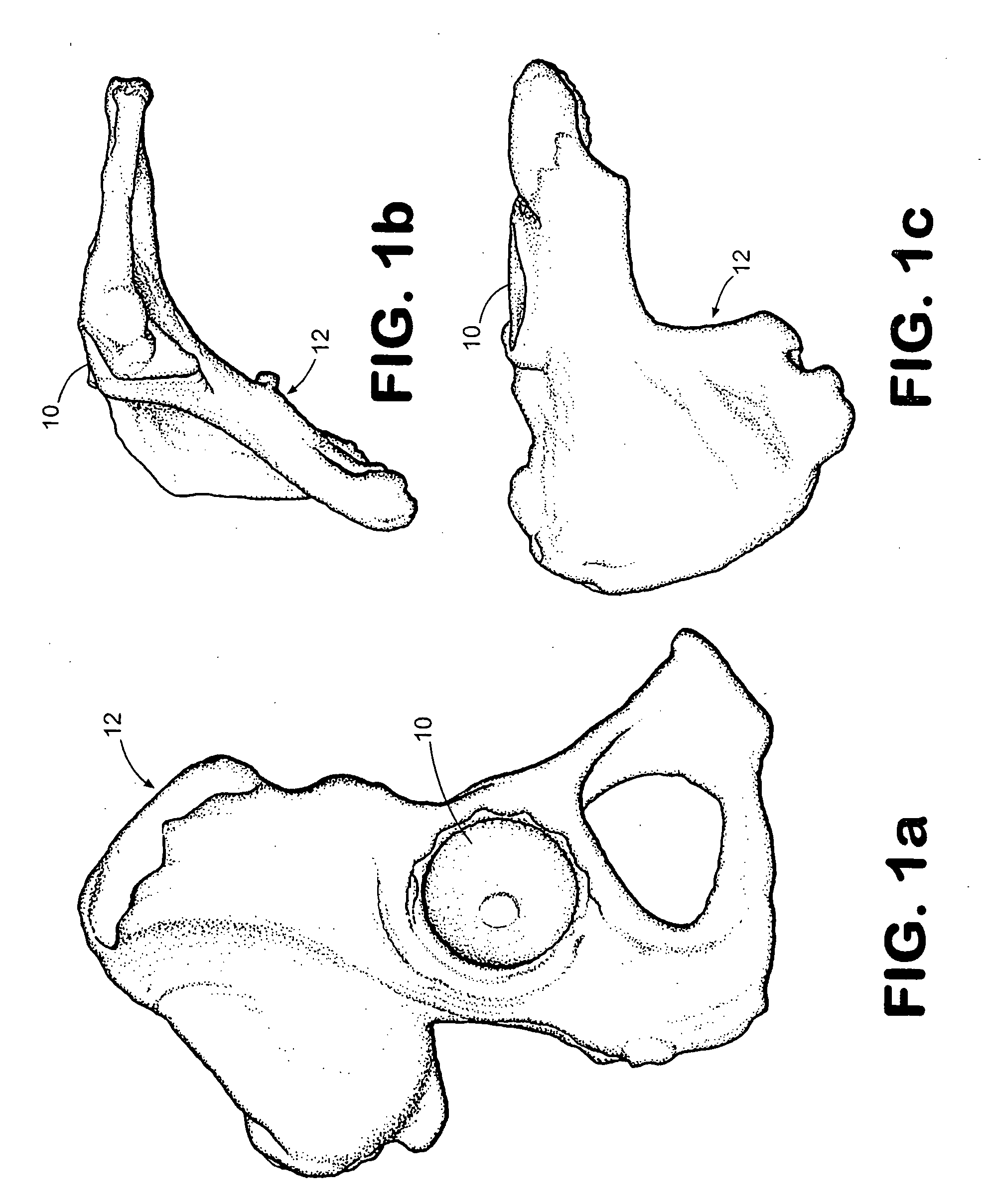
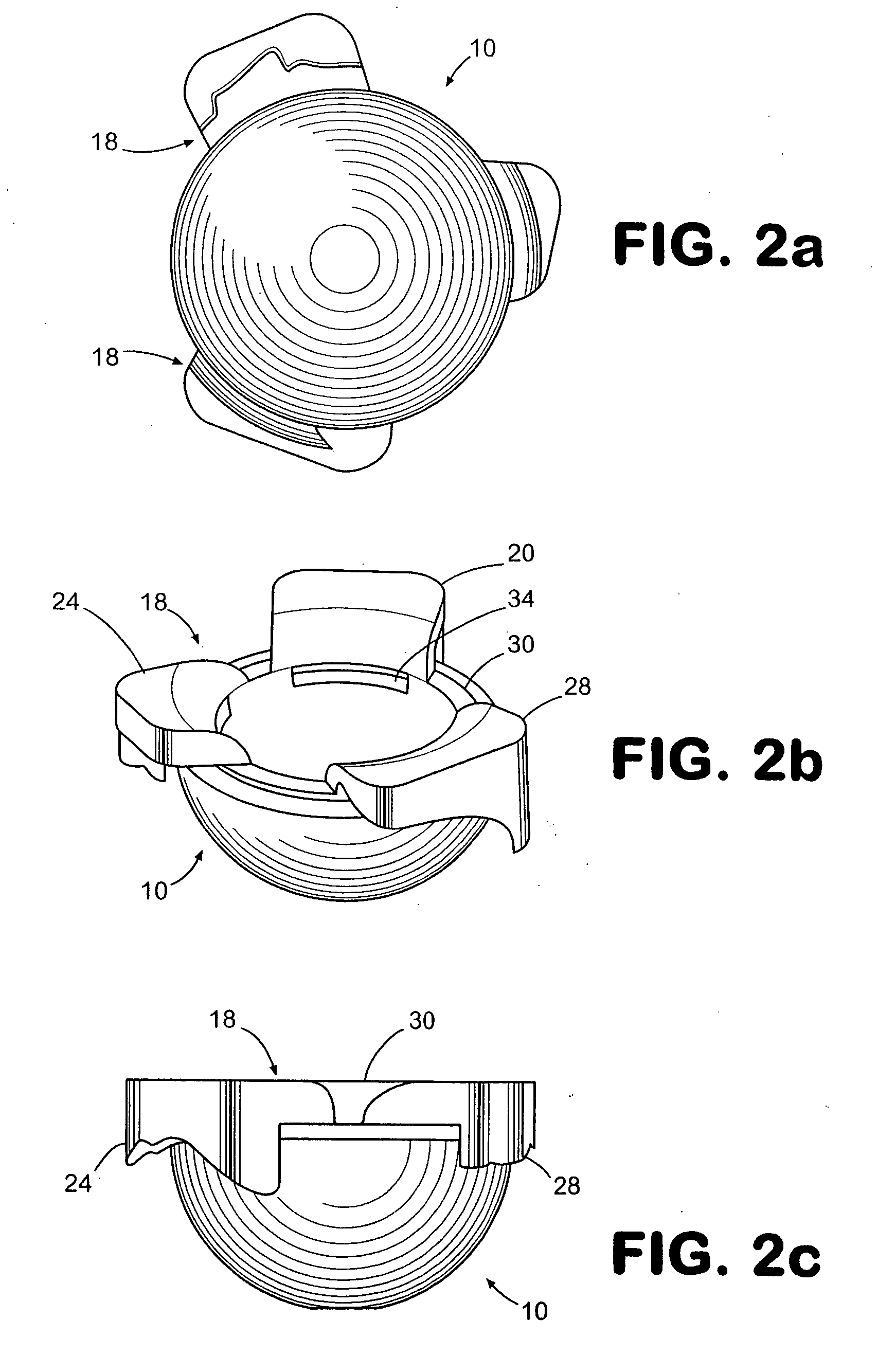
  • System and method of designing and manufacturing customized instrumentation for accurate implantation of prosthesis by utilizing computed tomography data
  • System and method of designing and manufacturing customized instrumentation for accurate implantation of prosthesis by utilizing computed tomography data
  • System and method of designing and manufacturing customized instrumentation for accurate implantation of prosthesis by utilizing computed tomography data

Examples


Embodiment Construction

[0035] For the purposes of promoting an understanding of the principles of the invention, reference will now be made to the environment and embodiments of the invention illustrated in the drawings and described in the following written specification. No limitation to the scope of the invention is thereby intended. The present invention includes any alterations and modifications to the illustrated embodiments and includes further applications of the principles of the invention as would normally occur to one skilled in the art to which this invention pertains.

[0036] In order to perform the method of the present invention, bone anatomical data is required. One way of obtaining this bone anatomical data is to perform a CT series on the patient in the area to be reconstructed. For a hip replacement, the patient is preferably scanned from the superior rim of the pelvis to the most inferior portion of the ischium in approximately 3 mm slices. Larger slices may not provide the detail in bo...


PUM


Abstract

A method and system may be used to design and control the manufacture of a surgical guide for implanting a prosthetic component. The system includes a bone surface image generator, a surgical guide image generator, and a surgical guide image converter. The bone surface image generator receives three dimensional bone anatomical data for a patient's bone and generates a bone surface image. The surgical guide image generator generates a surgical guide image from the bone surface image and an image of a prosthesis imposed on the bone surface image. The supporting structure of the generated surgical guide image conforms to the surface features of the three dimensional bone surface image. The surgical guide image is converted by surgical guide image converter into control data for operating a machine to form a surgical guide that corresponds to the surgical guide image.

Description

FIELD OF THE INVENTION [0001] The present invention relates to prosthetic systems for the replacement of joints or portions thereof. More particularly, the invention concerns customized instrumentation, and a method of designing and manufacturing such instrumentation based upon computed tomography data obtained from the patient. BACKGROUND OF THE INVENTION [0002] For treatment of various problems with the shoulder and hip such as degenerative arthritis and trauma, one method of providing relief to a patient is to replace the articulating surfaces of a diseased joint with an artificial or prosthetic joint. In the case of a shoulder, the humerus and glenoid articulating surfaces may be replaced. In the case of a hip, the femur and acetabulum articulating surfaces may be replaced. [0003] In such replacement, pain relief, increased motion and anatomic reconstruction of the shoulder or hip joint are goals of the orthopaedic surgeon. With multiple variations in human anatomy, prosthetic s...

Claims


Application Information

Patent Timeline
IPC IPC(8): A61B17/00A61B17/15A61B17/17A61B19/00A61F2/30A61F2/34A61F2/36A61F2/40
CPCA61B17/15A61F2002/4633A61B17/1746A61B17/175A61B19/50A61B19/5225A61B2017/00526A61F2/34A61F2/36A61F2/367A61F2/4059A61F2/4081A61F2002/30948A61F2002/30952A61F2002/30962A61F2002/343A61F2002/3611A61F2002/3625A61F2002/3631A61B17/17Y10S128/92Y10S623/923Y10S623/911A61B34/10A61B90/37B33Y80/00B33Y50/00
Inventor ROOSE, JEFFREY ROBERT
Owner DEPUY PROD INC
Why Eureka
Try Eureka