Fluid infusion apparatus with an insulated patient line tubing for preventing heat loss

a technology of fluid infusion apparatus and patient line, which is applied in the direction of contraceptives, other medical devices, therapeutic cooling, etc., can solve the problems of heat loss, limitations of this concept, and inability to warm fluids

Inactive Publication Date: 2005-07-07
MALLINCKRODT INC
View PDF21 Cites 51 Cited by
  • Summary
  • Abstract
  • Description
  • Claims
  • Application Information

AI Technical Summary

Benefits of technology

[0009] An improved fluid warming and infusion system is provided by the present invention. According to one embodiment, the fluid warming and infusion system includes a container for storing a fluid to be infused into a patient, a fluid warmer for warming the fluid prior to the fluid being infused into the patient, a tubing for delivering the fluid to the patient after the fluid has been warmed by the fluid warmer, and a patient insertion device (e.g., a needle or the like), which is connected to a distal end of the tubing, for insertion into the patient, wherein, after being warmed by the fluid warmer, the fluid flows through the tubing and is delivered into the patient by the insertion device (the tubing itself is not inserted into the patient). Advantageously, the tubing includes a substantially thermally insulating component for use as a thermal insulator in preventing the fluid from losing a substantial amount of heat as the fluid flows through the tubing.

Problems solved by technology

In the case of lower flow rates for adults, the amount of infused fluid when compared to the mass of the patient is generally deemed to be insignificant, and so warming of the fluid is not practiced.
This heat loss is problematic, particularly when the fluid flow rate is about 10 mL / min or less.
However, there are limitations to this concept.
Additionally, in very small diameters, there is a pressure build up due to the resistance of flow in a restricted cross sectional area.

Method used


Image

  • Fluid infusion apparatus with an insulated patient line tubing for preventing heat loss
  • Fluid infusion apparatus with an insulated patient line tubing for preventing heat loss
  • Fluid infusion apparatus with an insulated patient line tubing for preventing heat loss

Examples


Embodiment Construction

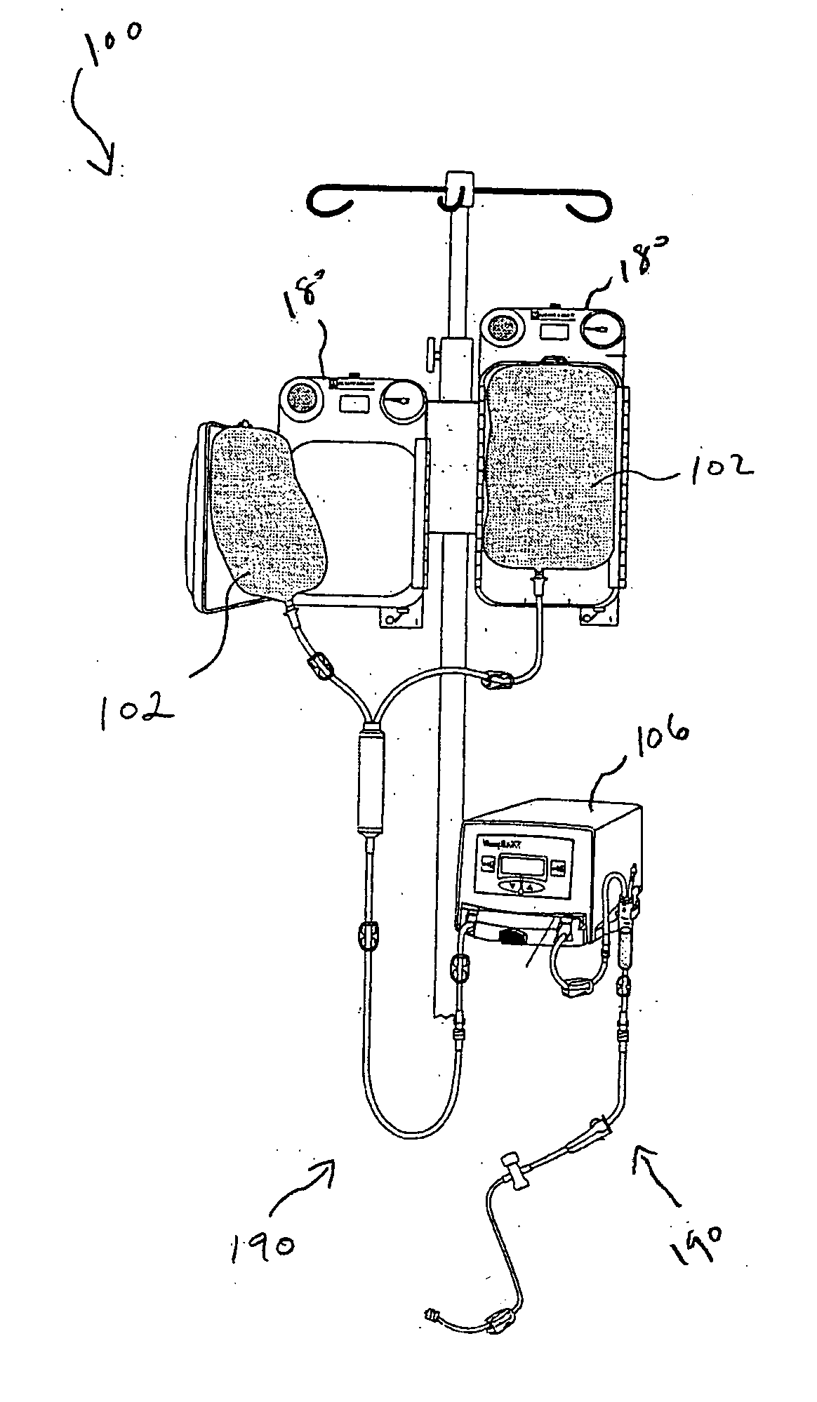
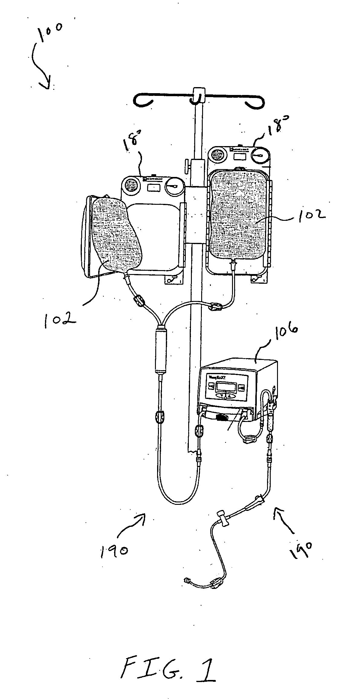
[0021]FIG. 1 shows a fluid warming and infusion system 100 according to one embodiment of the invention. As shown in FIG. 1, fluid warming and infusion system 100 includes a container 102 for holding a fluid, a fluid warmer 106 for transferring heat to the fluid, and fluid administration set 190 that is configured for use with fluid warmer 106. Container 102 is any suitable container for holding fluids, and, in one embodiment, fluid warmer 106 is the Warmflow® FW-588 fluid warmer available from Tyco Healthcare Group LP of Pleasanton, Calif. System 100 may include a pressure infusor 180 for forcing fluid to flow out of container 102 and into fluid administration set 190, however, in other embodiments, system 100 relies solely on gravity for this purpose.

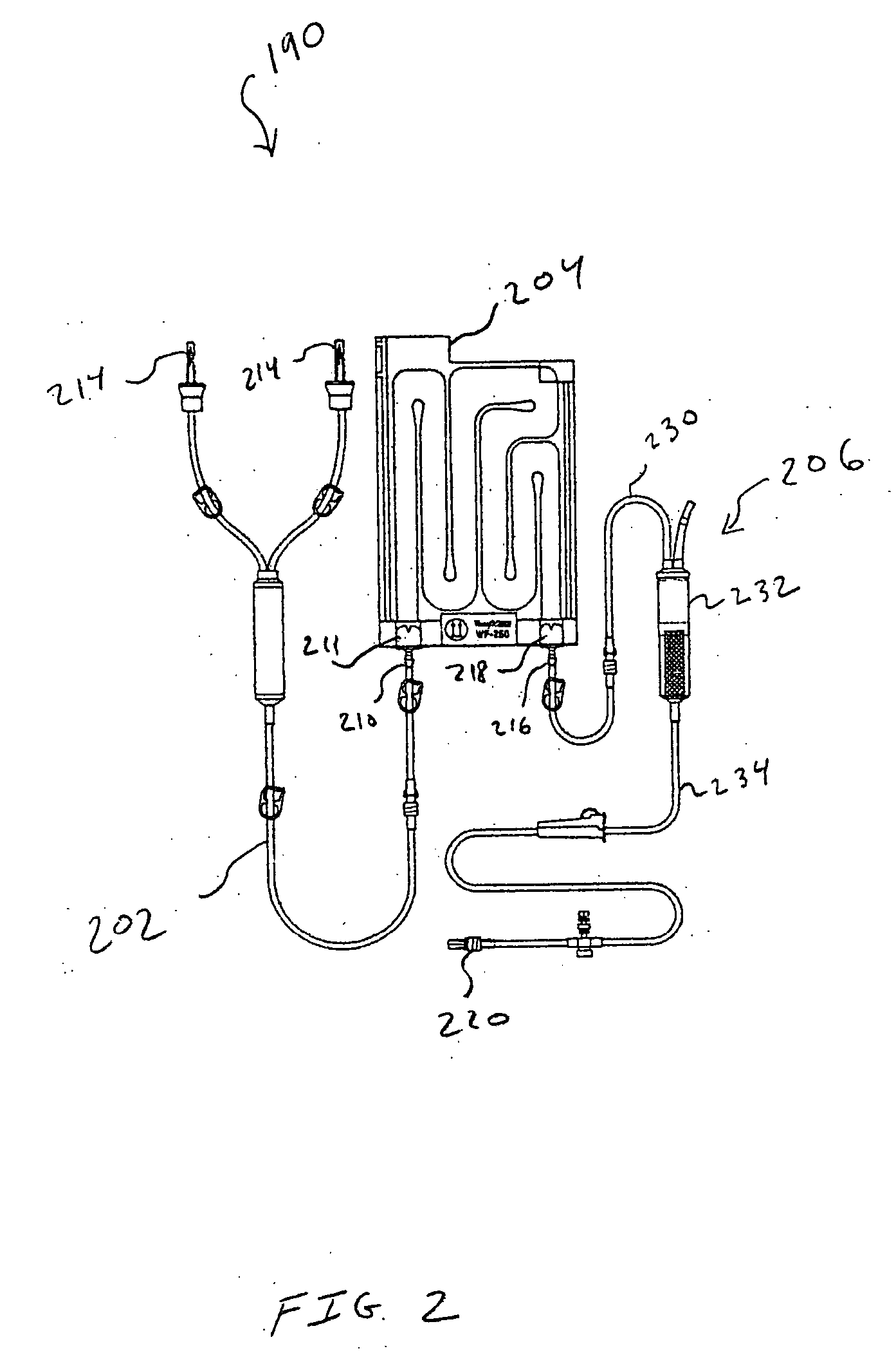
[0022]FIG. 2 is a schematic diagram further illustrating fluid administration set 190. As shown in FIG. 2, fluid administration set 190 includes a fluid line 202, a heat exchanger cassette 204, and a patient line 206. Heat exchanger ...


PUM


Abstract

A fluid warming and infusion system. According to one embodiment, the fluid warming and infusion system includes a container for storing a fluid to be infused into a patient, a fluid warmer for warming the fluid prior to the fluid being infused into the patient, a tubing for delivering the fluid to the patient after the fluid has been warmed by the fluid warmer, and a patient insertion device (e.g., a needle, or the like), which is connected to a distal end of the tubing, for insertion into the patient. After being warmed by the fluid warmer, the fluid flows through the tubing and is delivered into the patient by the insertion device. The tube includes a substantially thermally insulating component that prevents the warmed fluid from losing a substantial amount of heat as the fluid flows through the tube.

Description

BACKGROUND OF THE INVENTION [0001] 1. Field of the Invention [0002] The present invention relates generally to the field of intravenous fluid delivery. [0003] 2. Description of the Background Art [0004] Intravenous fluid delivery systems are systems used to infuse a fluid into the circulatory system of a patient. This may be done as part of medical treatment. The infusion may include infusion of fluids such as whole blood or blood components, saline solution, medications, or the like. [0005] The warming of fluids that are infused into patients intravenously is a standard of care for operating room procedures where the flow rates are typically above about 13-15 mL / min. In the case of lower flow rates for adults, the amount of infused fluid when compared to the mass of the patient is generally deemed to be insignificant, and so warming of the fluid is not practiced. In the case of pediatric and neonatal patients, the comparison is different, and flow rate of less than 13-15 mL / min, do...

Claims


Application Information

Patent Timeline
Patent Type & Authority Applications(United States)
IPC IPC(8): A61M5/44
CPCA61M2205/3633A61M5/445A61M5/44
Inventor MARTENS, PAUL WILLIAMCOAKLEY, JOSEPH
Owner MALLINCKRODT INC
Why Eureka
Try Eureka